Analog signals exchange - VFD->LOGO

rQx

Lifetime Supporting Member
Join Date
Oct 2010
Location
Trelleborg
Posts
1,051
Hi!

I have a VFD and a Siemens LOGO.
The VFD send the speed feedback 0-10V to my LOGO.
The LOGO send the speed setpoint 4-20mA to the VFD.

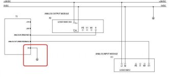
How would you set this up regarding that we use two power supplys (the VFDs and the LOGOs). Both power supply are grounded so the -24VDC have the same potential.

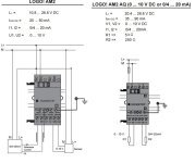
The examples in the manuals only state how to connect a 2-wire sensor with the same supply as the LOGO/VFD.

Naturally it works if I pull a wire from the logo to the VFD and the other way around since it have both ends grounded. But is this the best/a good solution?

Should I maybe connect the 0V on both ends?

What I am worried about is that if I connect and have reference to ground it will get noise from the VFD.

/Tim
 
Here is a drawing of my concern, and a jpg of the manual

Example.jpg
 

Attachments

  • Example.pdf
    9.5 KB · Views: 41
What type of drive are you using?

I know on the Siemens Micromaster440 drives they have an option to use an external power supply source.

Not sure if all do, but would think they would give you this option for when your using the drive in conjuction with PLCs.

I tried to download the quick start quide to post for you but we are in rough seas and I dont think the satlink dish is having a good time of it, as I cant load the PDF.

If you can download the "Siemens Micromaster440 Quick Start Guide" you can see an example of this on page #42.

BCS
 
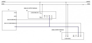
please refer the attachment

You can ground the 0V of the parker drive, but you mean in this case we shouldn't? I also noticed that you removed the grounding of our power supply, what is the meaning of this? We don't want floating reference thats why we connect it to ground.

I understand the analog input from VFD to LOGO analog input. Since we use power from the VFD we have to have reference to the 0V of the VFD aswell to the LOGO.

But the analog signal from the LOGO analog ouput, here it's using power from external power supply (supply of the analog output module) to the VFD. You mean that the current will flow from LOGO to VFD analog input, to VFD 0v and back to the analog output module?

I had one thought that I should connect the 0V of the VFD with the 0V of the power supply to get the same reference and then have it grounded only on one side (the power supply side)
 
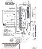
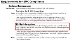
Base on User Manual the Parker SSD 650 Control Terminal 0V can connect earth/ground,

but if we refer to page 10-1 (attachment EARTH-2),

how to separately the earth ?

EARTH_1.jpg EARTH_2.JPG
 
This is when we have two drives, but maybe it applies to when we have one VFD and one power supply also. I think that this:

I should connect the 0V of the VFD with the 0V of the power supply to get the same reference and then have it grounded only on one side (the power supply side)

Is the most correct
 

Similar Topics

I'm looking for some opinions here. Typically for analog signals, we use a twisted pair wire with a drain shield. However, am I correct in...
Replies
5
Views
2,176
Using RSLogix 5000 version 20.05 with a 1769-IF8 analog card set to 4ma-20ms which is set to engineering units with a 10hz filter. I am wondering...
Replies
4
Views
3,015
I would like to enquire for a product as a solution for our on-going project. We need to transfer some analogue signals (QTY:08 / 4-20mA ) from...
Replies
11
Views
3,859
We worked in a sewage treatment plant and take care of their plc work. They have an issue with noise some of the analog signals in the plant. When...
Replies
19
Views
7,108
For the first time I have a load of analog signals being transferred into my Control Logix system via Modbus. I have sent analog to a DCS via...
Replies
1
Views
2,916
Back
Top Bottom