Behaviour of Micrologix 1400 Outputs during startup

rmb550

Member
Join Date
Nov 2009
Location
Ontario
Posts
86
Hi All,
I was testing the effects today of my processor losing power while running, and it appears that when power is restored the outputs resume the state they were in prior to the power loss. This is problematic as there is an output that during normal operation is ON and needs to be OFF on power up. I tried using the First Scan bit S:1/15 to set this output OFF during the First Scan, but it appears the output actually comes on PRIOR to the processor executing the First Scan.
I know that Horner PLC's allow one to configure this behaviour, but I have no idea how to accomplish this with the Micrologix.
Has anyone done this before?
Thanks,
rmb550
 
If the actual output command is in a OTL (L) command the default behavior will be to start up in the last state. If you want it to be off make sure it's addressed as an OTE (even if the conditions are the result of a latch). Use the 'First Scan' bit to kill any undesired latches.
 
please tell us more about this particular output that's giving you the problem ... specifically, what type of field device is it? ... when you say that it "comes on" do you mean that it comes on and then STAYS ON? - or does it just get a quick pulse on and then immediately goes back off again? ...
 
More Details

Thanks for both chiming in.
The attachment shows the relevant ladder lines.
The Output is an OTE. In the shown logic, the N7:32/x's are latching, while the N7:31/0 and the O:3/0 are both non-latching.
The output feeds a signal to a proprietary in-house designed controller board.
I would have thought that after resumption of power to the PLC, both N7:31/0 and O:3/0 would be at logic 0.
Any further thoughts gladly welcomed.
rmb550
 
I would have thought that after resumption of power to the PLC, both N7:31/0 and O:3/0 would be at logic 0.
They should be cleared during prescan, but if the logic that turns on N7:32/8 is an OTL, MOV or other non-OTE instruction, meaning that it is left as-is during prescan, so during first scan it may be true and therefore N7:31/0 and O:3/0 may turn right back on.

It could be an order of operations issue that allows this to happen. Can you zip and post the whole .rss file?
 
from WAY out in left field ...

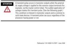
take a look at the section "Transistor Output Transient Pulses" which starts on page 51 of the following manual ...

http://literature.rockwellautomation.com/idc/groups/literature/documents/um/1747-um011_-en-p.pdf

I'm sorry that I don't have time to follow this all the way through right now, but I'd bet (pocket change only) that your field device is reacting to a "transient pulse" from your controller's output ... keep in mind that the type of "pulse" I'm talking about will happen EVEN IF THE LADDER LOGIC HAS THE OUTPUT TURNED OFF ...

this is a weird "beyond beginner" situation that can show up when a PLC is being used to "control" some field device which is capable of responding to a very quick pulse ... that's why I wanted to know more about your particular field device ... sounds like your "proprietary in-house designed controller board" probably fits into that category ...

PS Edit: if I'm on the right track with this line of reasoning, I seem to remember being able to duplicate a "trasient pulse" with an output module just lying on a bench ... specifically, even without being installed in a chassis, the module would send out a quick pulse as soon as its output circuits were powered up ... in simplest terms, if this DOES turn out to be your problem, then NOTHING that you can do in the PLC's ladder logic is going to solve your problem ... disclaimer: this paragraph is based on my feeble memory of troubleshooting a similar problem many years ago ... your mileage may vary ...

hope this helps ... wish I had more time to play ...

transient_pulse.JPG
 
Last edited:
Ron has asked the most important question - is the output "pulsing on then going off", or "coming on and staying on".

With the logic as shown, and your description of the latching nature of the N7:32 bits, then this is what I would expect the controller to do...

On resumption of power, after the power-on self-testing, and prior to the first proper scan of the logic, it performs a "pre-scan", during which time all data-table addresses associated with non-retentive outputs (eg. OTE's) will be reset to zero. the bits that are "latching", as you describe, in N7:32 will not be reset to zero.

After the "pre-scan", the controller will scan the logic proper, and during that first scan, will see that N7:32/8 is ON, and will turn on N7:31/0 on your first rung.

Then your second rung is executed, and N7:31/0 will turn on your output, O:3/0.

If you don't want your output to come on again after a power-on, you will need to program a reset of N7:32/8
 
Sorry I did not answer a key question earlier - yes the output turns on transiently then turns off. I am guessing that this happens PRIOR to the execution of the ladder logic, and hence I am concluding that there is nothing I can do within the ladder logic to prevent this from happening. This is not good for this device. I am not sure what to do next.
Thanks for all the good ideas!
rmb550
 
The output feeds a signal to a proprietary in-house designed controller board.

Is the actual bit in the PLC turning on? Or are you seeing the output indicator led pulse on power up? If the latter place the PLC in program mode and cycle power and see what happens. If the light still pulses then disconnect your proprietary in house designed controller board and try the test again. Then let us know what happened.
 
Last edited:
This is not good for this device. I am not sure what to do next.

you might consider making SURE that the power source to the PLC's output circuits is alread "fired up" BEFORE making a connection to the other board ... (note that I am NOT saying that the OUTPUT is turned on - only that the power supply is turned on) ...

in other words, don't let the board already be "waiting for a signal" when you first turn on the source of "output power" to the PLC ...

you might be able to put a set of Normally-Open relay contacts into the PLC-to-board signal circuit - and only turn on the relay coil with a separate PLC output AFTER the PLC'S output power supply has already been ON for a few seconds ...
 
Last edited:
another thought:

you might be able to tweak the board's design to "bebounce" that particular input signal ... in other words, fix it so that the input signal needs to be ON for longer than just a quick "pulse" before it gets counted as a valid signal ...
 
I am using a 220VAC supply to power the PLC and separate 24VDC supplies for the modules. The experiment here was to observe the behaviour if the PLC power cycles, so we cycled only the 220VAC to the PLC main module - all other devices remained powered on. I should add that the entire exercise MAY be somewhat academic as we power the whole kit and kaboodle from a UPS - however it still COULD happen that the PLC drops out unintentionally.
To answer some additional questions, I am seeing the indicator LED on the module come on and my board is seeing the actual signal from the module. I am assuming the bit in the PLC is turning on since the output definitely turns on, but I am not sure whether the RSLogix is even communicating at that point. Since it all does seem to happen before the first scan I am not sure what to do.
I did program a N/C contact addressed to S:1/15 (First Scan) in series with the output in the ladder - but I still got the pulse, which lead me to this thinking that it happens BEFORE the first scan.
If those modules can be sending spurious start-up pulses then I REALLY have some thinking on my hands....
rmb550
 
trust me, I am NOT trying to make this harder than it has to be, but it sounds like you're doing some "research and development" here ... with that in mind, let me offer some friendly advice on testing for "power cycles" to the PLC ...

in some cases it makes a BIG difference whether:

(A) the PLC processor's power stays off for MORE THAN several seconds ...

or ...

(B) the PLC processor's power stays off for LESS THAN several seconds ...

be sure to test for both situations ...

basic reason: if the power stays off for LESS THAN several seconds, then most PLCs KEEP RIGHT ON SCANNING – and so the "First Pass" bit (S:1/15) doesn't actually get "fired" the way the programmer intended ... also, it's possible that any "normally closed" type inputs might appear to the PLC as an OFF signal ... specifically, if there's suddenly no current flowing through a particular input (due to the power failure) the PLC can interpret that as an OFF signal during the time that it keeps on scanning ... that can play havoc with a program ... worse yet, the intermittent nature of the problem can make it a nightmare to debug – unless you know what to look for ...

words of wisdom: make sure that your testing procedures incorporate both "power failures" – AND – "power flickers" ...

if you're "into" this type of stuff, you might want to take a look at the "Surprises at Go-To-Run" E-Mail Quiz on my website ... you can get there from a link near the bottom of the "Sample Lessons" page ...

good luck with your project ... I've REALLY got to get back to work now ...
 
Ron,
I certainly don't have the feeling that you are making things difficult - on the contrary I am quite grateful and appreciative of the help. The power to the PLC was off for over a minute. It's not really R&D - I am testing a device that will be shipped to the customer shortly.
rmb550
 
I am assuming the bit in the PLC is turning on since the output definitely turns on, but I am not sure whether the RSLogix is even communicating at that point.
This is exactly the reason I suggested you put the PLC in program mode and perform the test. The test will determine if you are seeing the hardware respond to the power cycle or seeing the program respond to the power cycle.


Since it all does seem to happen before the first scan I am not sure what to do. I did program a N/C contact addressed to S:1/15 (First Scan) in series with the output in the ladder - but I still got the pulse, which lead me to this thinking that it happens BEFORE the first scan.
If that is what is happening then no matter how many first scan bit XICs or XIOs you program you aren't going to fix it with software.


If those modules can be sending spurious start-up pulses then I REALLY have some thinking on my hands....
rmb550
Disconnect your in house board and do the power cycle test. Are you absolutely positively sure that board is not back feeding the pulse? Knuckle down and do the test and eliminate it as a possibility. Then we can discuss other options.
 

Similar Topics

Hi guys this is my first post on this forum but I have been a long time browser. I have this issue with a micrologix 1500, it's a strange one...
Replies
4
Views
2,103
Hi, I have a 1794-IE12 FlexIO module connected via Ethernet/IP to a 1769-L24ER CompactLogix controller. The inputs are configured for 0-20mA and...
Replies
3
Views
2,369
Hi All, I am using a Red Lion graphite G12 panel to draw a scatter graph, all works well until I run this code every morning to reset the arrays...
Replies
19
Views
6,321
Hello Codesys wizards, once again a cry for help from this mind with limited understanding of Codesys. I have almost completed an application that...
Replies
6
Views
3,245
I recently discovered that when downloading an online edit [S7-1500] that requires the initialization of the modified FB's iDB, an IEC timer whose...
Replies
36
Views
11,926
Back
Top Bottom