CLX RIO PLC5 Analog

if you're trying to nail down the series of the IFE and ASB then you need to physically look at the labels on the sides of the modules ... specifically, you can't get the exact information over any type of network connection ...

Gather the Series letters and part numbers of everything, including that power supply. Note the DIP switch settings both on the 1771 backplane and on the 1771-ASB module.

yes ... yes ... yes ...

I have most (if not ALL) of these parts in my lab equipment ... if I get time tomorrow I might have a chance to duplicate your setup and see if it works OK ... I won't be able to do that without knowing exactly how your system is set up ... specifically, saying that the DIP switches (etc.) are "correct" doesn't really help me duplicate your setup ...


Also, please remember that 1771 backplanes need to be powered down before you remove or insert modules !

The RUN light on a 1771-IFE generally blinks after a power cycle until it receives a valid BTW to configure it.
 
Ok. First off my bad! The initial IFE card that was in my set up was infact a IFE/A rev C so I was a little confused. I now have replace this with and IFE/C. No longer getting that same error. Again the IFE messages are EN then DN. I know I don't need to constantly write the data to the mod but I will figure the best way to at least constantly read the data. If i take part of my logic out it sits with the EN on the read all the time and never finishes to DN so I will write that and am not worried. I really appreciate all the help. Now the only final thing is where do I set my pointer for the data? In PLC5 you could go into the configurationa and see what integer it was writing the data to. Where is it in this CLX system? Hopefully my OFE works. I currently don't have any wiring coming off of either and might take me a bit to scrounge up a swing arm for both these. Is there a way that I can test it internally/theoretically. Type a number somewhere and make sure that it is reading that? I am not all that great when it comes to physically wiring PLC's to the inputs and outputs we have electricians out here that do that work for me and I literally just do the ladder logic. Thanks for the help again
 
The initial IFE card that was in my set up was infact a IFE/A rev C so I was a little confused. I now have replace this with and IFE/C.

ah! - details! ...

sounds like your IFE/A was choking on those extra two configuration words ... that apparently was causing the Message command to give an error when the Block Transfer Write couldn't be properly completed ...

No longer getting that same error.

well, that's a step in the right direction ...

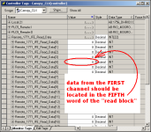
Now the only final thing is where do I set my pointer for the data?

based on the ACD file that you posted earlier, the screen shot below should help ... beyond that, the following manual should be helpful ...

http://literature.rockwellautomation.com/idc/groups/literature/documents/um/1771-um663_-en-p.pdf

see Figure 5.1 on page 5-1 ...

of course, until you fix the "scaling" issues you shouldn't expect to see anything exciting ... Zero to Zero is pretty much going to end up looking like Zero ...

Is there a way that I can test it internally/theoretically. Type a number somewhere and make sure that it is reading that?

no, not really ...

I am not all that great when it comes to physically wiring PLC's to the inputs and outputs we have electricians out here that do that work for me

make sure that they know whether you're going to be programming the IFE Input module for DIFFERENTIAL or for SINGLE-ENDED operation ... the wiring will be different for each method ...

also ...

there are JUMPERS located inside the IFE module – and they'll need to be positioned correctly for the type of wiring (and programming) that you decide to use ...

Thanks for the help again

you're welcome – and good luck with the rest of your project ...

.

channel_location.PNG
 
Last edited:
Ok that was kind of what I was thinking. Reading manuals was just starting to make me go bug eyed. Again I really appreciate the help. Last question if you would indulge me is are the scaling values that I put in. Cand they just be entered as a decimal in the word or do I have to use BCD and set the individual bits again?
 
the settings below MIGHT (or might not) help ...

it all depends on whether you're using DIFFERENTIAL or SINGLE-ENDED operation ...

with DIFFERENTIAL you'll get 8 input channels on the IFE module ...

with SINGLE-ENDED you'll get 16 input channels on the IFE module ...

the settings that I've shown are as "plain vanilla" as you're likely to get ... DIFFERENTIAL – two's complement binary numbering – and eight channels set up for 0 to 4095 scaling ...

this is the reason why I asked for an existing RSP program file in an earlier post ... most "been-burned-before" people will take the data from a WORKING PLC-5 installation – and then manually copy that into the ControlLogix data locations ...

.

scaling_data.PNG
 
Last edited:
ok so you are required to use the BCD format and not just a decimal. I did see some sample logic somewhere they had juse used the decimal number but was suspect. I see that without a swing arm my input module was already reading a value of 1053 and 1616 on the first 2 channels with zeros in both min and max scaling which tells me either with zeros in both that it will recieve a raw number that is unscaled and uses the 0-4095 as a base or I have a lot of noise
 
Ron and Mike you have both been AMAZING. I am relatively new to the indepth PLC world. I have been doing this fulltime for approximately 4 months and can work fairly comfortably in either system and dabled a bit with the SLC but intermixing the two systems and learning things like modbus and prosoft I am a novice at best. I will definitely be back for additional help later when required. I will also try and post some solutions for people with problems if I know them.

To the others that attempted to help it is great to see such activity on the forum and having multiple sources of help.
 
ok so you are required to use the BCD format and not just a decimal.

let's say it THIS way instead ... the 1771-IFE technology is about 25-30 years old ... way-back-then, BCD (Binary Coded Decimal) was the going thing ... this old-style (but still VERY popular) module EXPECTS/DEMANDS that its configuration data be expressed in a BCD format ... nothing else will satisfy the module ...

but ...

whenever we humans look at the BCD scaling data value 4095 in DECIMAL form (the default numbering format for most of our newer systems) we see the number 16533 ...

so ...

as long as you keep your data table format set up for "decimal" you can just type the data in as 16533 – secure in the knowledge that when that same data gets written into the IFE module, the module will interpret/accept/recognize the data value as 4095 ...

I see that without a swing arm my input module was already reading a value of 1053 and 1616 on the first 2 channels

I wouldn't go too far down that particular road if I were you ...

until the module has been properly configured (scaled, etc.) – and properly wired to an input signal, then any data readings that you might see are totally/completely meaningless ... you might be picking up signals from a nearby fluorescent light fixture, etc. ...
 
whenever we humans look at the BCD scaling data value 4095 in DECIMAL form (the default numbering format for most of our newer systems) we see the number 16533 ...

so ...

as long as you keep your data table format set up for "decimal" you can just type the data in as 16533 – secure in the knowledge that when that same data gets written into the IFE module, the module will interpret/accept/recognize the data value as 4095 ...

16533 is what 4095 is when you read a decimal number out of the BCD if you are not aware that the format is BCD then 16533 doesn't mean a whole lot and I would assume that it would be the raw number. Knowing that when BCD of 4095 is inserted and read as a standard binary number as 16533. What I was getting at was that I needed to use 16533(BCD) and not just type in 4095 which is a significantly different number(which can not be used in the BCD format because 9 is the highest number achieved in BCD and it is 1111 1111 1111) 16533 im sure as you know but others reading may not is (0100 0000 1001 0101)= 4 0 9 5

As far as going down that road I was only making the statement saying that i was getting readings which with the current configuration did not make sense unless one of those 2 things was happening.(that 0 in the max scaling is a default OR that there was a lot of noise) I was leaning more towards the noise.

You are a smart guy and I was not meaning this to be insulting your intelligence in anyway but I know that some not as versed in logic/binary read these as well and was just providing extra information for those who don't know.
 
You are a smart guy

well, that's highly debatable – and I'm not always on the same side of the debate ...

I was not meaning this to be insulting your intelligence in anyway

I didn't take it that way ...

actually I can't be "insulted" ... I answer my own phone when it rings – I wash the dishes after supper – I do my own laundry – my wife gives me a $20 allowance once a week IF I behave myself ...

it's hard to build an ego on a foundation like that ...

I know that some not as versed in logic/binary read these as well and was just providing extra information for those who don't know.

I apologize for any misunderstanding ... I thought that you were asking for more advice on how to set these modules up ...

peace ...

 
Jordon, Not sure how far you have progressed.
I think the issue might be the logic, Here is your code modified to match the PLC-5 example from the manual:

IFE_CLX.jpg

Remember you have two issues to deal with:
1. Get the BTR / BTW working - that is get DN bits.
2. Once you have the DN bits working - deal with the configuration data.

If you get a DN bit on the read but the data does not look correct then it is a configuration issue. If you don't get a DN bit worry about that rather than the data.

My 2 cents.
 
Yea this is about what I have I will have to check into exactly what you have and what I have but it seems very similar but when I have my logic set up I toggle first scan bit and if it stays energized the system goes back and forth reading the BTW and BTR. I basically need to just get it so it scans just the BTR after the first scan. Once i toggle the first scan off it just keeps the EN for the BTR and never goes DN. That is a matter of just tweeking the bits in the correct order and something I just need more then 2 min to get. until that time I am happy that I was being stupid the whole time and had the configuration for the wrong module.

The reason I was fixated on the configuration was because unless you "semi set up" the module it won't even talk to it. This is why I was having issues with the msg. Once I got the configuration semi set up I can tweek it to what I want for scaling and min and max after as long as the MSG do actually produce a DN bit. Thanks for you 2 cents. If I collected all of them I could have an extra couple bucks from your guys' fountain of knowledge.
 
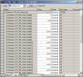
Here's a tip for working with the BCD data required for the module configuration.

If you change the "style" of the INT array tag to Hex (Edit Tags tab - see 1st pic). Then on the "Monitor Tags" all the values will be displayed, and you can enter them, as BCD (see second pic).

Any location can be temporarily switched to any other radix, as required (also shown on pic #2).

TagEdit.jpg 2014-02-05_222543.jpg
 

Similar Topics

Can i terminate(put resistor in terminal of channel a)the blue hose of an existing plc5 dh+ network to a new 1756-dhrio in new clx rack without...
Replies
8
Views
2,736
Curious if this is possible. I am working on a PLC5 to CLX conversion. Due to panel space limitations and time I need to replace a small PLC5...
Replies
4
Views
3,502
Hey fellas, I did a search but didn't find anything that quite fit. I'm setting up a new CLX chassis (with processor) for a new project. I need...
Replies
5
Views
5,543
I am trying to send some datas from PLC-5 to control logix plc through 1756-DHRIO. When I go online to PLC-5, Message instruction gives error &...
Replies
15
Views
3,373
Upgraded a PLC-5/80 today to a CLX. There are 5 physical ASB modules for a total of 10 racks. All 10 are added in the CLX tree under the DHRIO...
Replies
14
Views
4,397
Back
Top Bottom