Configuration of s7-300 and s7.1200 via Profibus with CM1242-5 module

moggie

Lifetime Supporting Member
Join Date
Apr 2002
Location
Devon, England.
Posts
661
I have an S7 1212 with CM1242-5 Profibus module configured in TIA V13 to connect to an S7 315 2DP Profibus master.
The configuration is set up for 16 words of inputs & outputs, starting at IW200 & QW200
Whilst I can see the values of the words change is it possible to send bits?
For example -
In the S7 300
A M200.0
= Q200.0
And then see the Input Bit I 200.0 change state in the S7 1200?
 
We usually use a DB as a buffer, with bits and integers declared, and consequently move the entire DB to the output area.

Now you can use the individual bits in your program, but just deal with the integers when sending and receiving data.
 
In the 300, as long as you are addressing the words as IW and not PIW, you should be able to address the individual bits as well. You can write to the process image as bits, but you cannot if you are writing to IO outside the process image.

In the 1200, the process image table is the entire IO area, so you don't need to worry about that. However, I've never used any of the DP communication cards, so I don't know if there are any complications there.
 
So I assume this should work (I cannot test until tuesday) -
L PIW 200
T IW 200
Then I can use the individual bits within my program?
Example -
....
A I 200.7
Etc
....
A M100.5
=Q 200.2
At the end of the program
L QW 200
T PQW 200
 
Since you are using STL, I assume you are talking about IW200 in the S7-300, and not the 1200.

What you listed might technically work (I'm not sure), but it isn't really how it is supposed to be used.

Commands like PIW/PQW do a periphery read/write to go directly to the IO, at that specific point in the scan cycle. You can write Words, Double words (and maybe single bytes, too), via this method, but not single bits.

You can also use two commands (I think SFC14/15?) to write larger blocks of data directly to the IO.

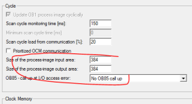
The PLC buffers some of this data in what is called the Process Image at the beginning/end of the scan cycle. This is how people generally access digital data, with the standard "read inputs, execute code, write outputs" PLC scan people are used to. However, the PLC only buffers the amount of data that you specify in the HW Config. Data in the Process Image can be accessed as bits, bytes, words, or double words. Anything above that must be accessed by periphery access.


A common situation I see is for the Process image to automatically cover the first 256 bytes of the input and output data, but you would need to check your HW Config to see what is being used for your PLC.

You say you have 16 bytes being transferred starting at 200. As long as the process image is set to at least 216, you can access each bit by the I200.7 style, without needing to do anything special.

If your PI is set to something lower, like 128, then you would need to either increase the PI setting or use a peripheral read to copy the data. YOu shouldn't copy to the PI, which is what you tried to do in your code. Generally speaking, it isn't a good practice to try to write to inputs or read from outputs. You should use a DB as a buffer instead, as boneless suggested. If you want, you could use the SFC's I mentioned to copy the whole 16 bytes at once.
 
Another thing to keep an eye on is the process image. Make sure your i/o is within this area.

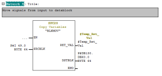
Here the block move I use.

BLKMOV.PNG Process.PNG
 

Similar Topics

Hi i using Kinetik 300 2097 driver control by EIP with using move absolute and incremental for motion , but i want to add same driver and motor as...
Replies
0
Views
37
I have Windows 7 Pro and am trying to configure ABs 9300-USBS USB to RS232 adapter. I have done it in Windows XP but am having problems with Win 7...
Replies
4
Views
2,289
Hi, I got two questios: There are two slave devices(SEL-787) from which I should read data via MODBUS RTU. I checked SEL-787 manual and it says...
Replies
14
Views
5,553
Is there a way to configure these starters without the faceplate? The customer did not buy any faceplates and the manual refers to different...
Replies
0
Views
2,148
Hi , I am looking for the solution, how to configure I/O of E300 . For example , Input 1 trigger Output 1, Input 2 trigger Output 2. In...
Replies
0
Views
1,294
Back
Top Bottom