Connecting a pressure sensor to a module

Georgiev96

Member
Join Date
Jul 2021
Location
Saarland
Posts
3
Dear community, i am new into the world of plc and i have really basic question about the properly connecting of a pressure sensor to a modul which does the current measurement and provides the powersupply. There is a lot of information in Internet but i am just still not sure if my wiring is correct, therefore i decided to ask before destroying the sensor or the module.

So, i have a 2 wire pressure sensor with 4...20mA output.
I have a module, which is measuring the current signal and gives the power supply to the sensor too.

So how do i connect them?

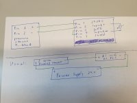
In the attached picture there is a description of the pins from the sensor and the pins of the module and the way how i would connect it.

Could someone pleas check it and tell if it is correct?

Thanks in advance!
20210708_105254.jpg
 
Hi, welcome to the forum!!
I would be sure to check to see if your AI card is sourcing or sinking. Also, be sure in the future to post what hardware (Rockwell, Siemens, AD, Schneider, etc) and software version you are configuring. It helps folks provide a more concise answer.
If you are using AB, there is a good article by Ron Beaufort on this forum regarding wiring of sink/source in AI and AO plus DI and DO. Search the forum for the article, and I have a copy of it that I can send you if you have problems.
You probably ought to respond with what PLC you have. Hope this helps.
 
Thanks a lot �� for the fast response!

I was not sure if i can give a lot of information, so that is not considered as advertising, therefore i didn't do it, but i will know for the future. Thanks!

Hier is the information:

The sensor is connected to the AI Modul X671333 from B&R.
The AI module is connected to a bus transmitter X20BT940 also from B&R.
THE bus transmitter is attached to the PLC B&R X20 CP 1584.

But from the PLC to the AI Module everything is connected correct.

The cable for the connection between the sensor and the AI module was provided but the pin jack which is connected to the AI module was not wired and i just need to wired it correctly.

Since the AI module provides the power for the sensor i would say that it has a sourcing input.
 
You drawing looks to have the same connections as mine. If the analog input is programmable make sure you set it for Current and not Voltage. The risk of destroying the sensor or module is generally very small. They are designed to live in an industrial environment and be wired by the average industrial sparky, so they make them robust. My customers have managed to destroy one or two, but they are often mechanical engineers and use the 'get a larger hammer' method of fault diagnosis, and like to weld metal right next to the sensors.

4-20 Connection.JPG
 
Thanks a lot �� for the fast response!

I was not sure if i can give a lot of information, so that is not considered as advertising, therefore i didn't do it, but i will know for the future. Thanks!

Hier is the information:

The sensor is connected to the AI Modul X671333 from B&R.
The AI module is connected to a bus transmitter X20BT940 also from B&R.
THE bus transmitter is attached to the PLC B&R X20 CP 1584.

But from the PLC to the AI Module everything is connected correct.

The cable for the connection between the sensor and the AI module was provided but the pin jack which is connected to the AI module was not wired and i just need to wired it correctly.

Since the AI module provides the power for the sensor i would say that it has a sourcing input.

Hi, no problem. I have no experience with the hardware you have, however it seems others have come to your rescue. Remember you'll probably need to scale your input in logic. Good luck!
 
Looking at their documentation (for the X67AI1333 module) I think your diagram will work. Their documentation is not very clear. They give you a 4 wire diagram and expect you to extrapolate from there. If you are in doubt then I would just give the rep or their tech support a call. I don't think you can damage the unit wiring it as you have shown. It looks like you will need to connect a supply voltage to the I/O power supply connection at the bottom left of the unit also.
 
Hello community,
it has worked! Thank you a lot for all of your help! It is really nice to know that there are people all over the world who are ready to help!

Thanks a lot! Sharing knowledge is power!
 

Similar Topics

Can anyone tell me how to connect a Presure Switch to a ANALOG I/O card on a SLC 500 and how to connect a KUBLER message display as well
Replies
2
Views
4,553
Good Day to all of you, this is my first post, i will try to explain as best as possible, english is not my natural language. I am performing an...
Replies
0
Views
46
I have been working on this for a while now and I can't seem to get it. I was finally able to view the 1500 on the PanelView under the serial...
Replies
1
Views
91
Hello, I was looking to store some values from our FactoryTalk Application using Datalog to a MariaDB. I see there is quite a bit of documentation...
Replies
1
Views
102
I haven't encountered problems connecting to a PLC through VM Ware but I am with this particular machine. I'm running Windows 7 on a Windows 10...
Replies
8
Views
235
Back
Top Bottom