eight_bools
Lifetime Supporting Member
Hey Guys,
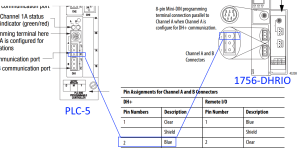
I am trying to setup a Control Logix gateway to add a DH+ network to our plant Ethernet network. I have never done this before and I am not winning. The DH+ network had 6 nodes (2-7) and have 5 SLC and one PLC5. Everything on the network is working except for the 1756-DHRIO (node 10).
We used daisy chain wiring to each machine with one end being the DHRIO and the other being a machine. Each end has a 150ohm terminating resistor. My problem is that the DHRIO card is not being recognized on the DH+ network and when I browse to the DHRIO through the ENBT card It does not show any other nodes. I also cannot connect directly to the DHRIO card using the 8 pin octal connector using the 1784-U2DHP. When I tried that in RSLinx it did not show up while browsing.
I triple checked all the rotary switches, and it shows as being node 10 and 56k baud like the rest of the network. At first I thought that the cable may be bad somewhere, but the terminating resistor is getting warm.
I am starting to think that the card is bad, I dont know where it came from (I found it in our “junk drawer” room). I just realized I didn’t try channel B and may try that on when I get back to work. The message on the card says something like channel b is not scanning and channel a node 10 no other nodes.
I updated to the frimware to the latest and installed all the EDS files from the Rockwell software. I tried setting up the routing tables, but am not sure if I am doing it right.
My question is do the routing tables have to be configured if I am not trying to message? All I want to do is be able to go online with them wirelessly using our plant network. The card is a 1756-DHRIO series E. It seems like the other nodes should still show up if all I am trying to do is browse in RSLinx.
Does anyone know if the routing tables are required to browse or have any other thoughts?
Thanks


