renan.musardo
Member
Hello everyone.
I'm trying to communicate a Controllogix L36ERM with a 1769-SM2 Modbus module to a Schneider-electric Altivar 312 Modbus motor inverter, however communications doesn't seen to work.
Here's what I already have:
Altivar 312 Configs:
Addresses: 31...36 (6 inverters, however, I'm trying to test only one until finding out the problem)
tFo: 8N1
tBr: 19K2
SR1: MdB
Inverter is signaling "nST" (Something like "waiting for input")
1769-SM2 Configs
5x / Controller (on DipSwitches)
At data parameters, I have:
CH1:
W#3 = 5 (Modbus Master)
W#4 = 31 (Node adress)
W#5 = 32 (Node adress)
W#9 = 1 (Baud rate = 19k2 bps)
W#10 = 0 (Format = 8N1)
W#11 = 50 (50 ms RX delay)
W#12 = 50 (50 ms TX delay)
W#13 = 5 (5 sec MSG timeout)
CH2/CH3: Same configs as above, except for node adresses.
I was trying to read the Communication words: W#3201/ W#3202, but I've received nothing (zero...)
The only thing I didn't checked was the cable. The SM2 module was like this:
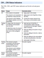
LED Module: Fixed Green
LED CH1: Off
LED CH2: Off
LED CH3: Off
The inverters are already installed in the client, four hours away from me , so I need to check the software and parameters first, before trying to check cabling.
The PLC is with me, so I can change parameters, however, I can't test with the inverter...
I appreciate any help and thanks in advance
I'm trying to communicate a Controllogix L36ERM with a 1769-SM2 Modbus module to a Schneider-electric Altivar 312 Modbus motor inverter, however communications doesn't seen to work.
Here's what I already have:
Altivar 312 Configs:
Addresses: 31...36 (6 inverters, however, I'm trying to test only one until finding out the problem)
tFo: 8N1
tBr: 19K2
SR1: MdB
Inverter is signaling "nST" (Something like "waiting for input")
1769-SM2 Configs
5x / Controller (on DipSwitches)
At data parameters, I have:
CH1:
W#3 = 5 (Modbus Master)
W#4 = 31 (Node adress)
W#5 = 32 (Node adress)
W#9 = 1 (Baud rate = 19k2 bps)
W#10 = 0 (Format = 8N1)
W#11 = 50 (50 ms RX delay)
W#12 = 50 (50 ms TX delay)
W#13 = 5 (5 sec MSG timeout)
CH2/CH3: Same configs as above, except for node adresses.
I was trying to read the Communication words: W#3201/ W#3202, but I've received nothing (zero...)
The only thing I didn't checked was the cable. The SM2 module was like this:
LED Module: Fixed Green
LED CH1: Off
LED CH2: Off
LED CH3: Off
The inverters are already installed in the client, four hours away from me
The PLC is with me, so I can change parameters, however, I can't test with the inverter...
I appreciate any help and thanks in advance


