Crimson Alarm resetting

UKAi

Member
Join Date
Feb 2022
Location
UK
Posts
22
Hi -
I was after a bit of feedback on the alarm resetting logic Im using in a Redlion HMI and 1200 PLC

resetlogic.png


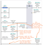
When the "alarm consecutive rejects" (light blue box -coil) goes true - I raise an alarm in the RL - when an operator hits accept button on the alarm page I write the reset contact (dark blue box NO) to 1.

When the "alarm consecutive rejects" (light blue box -coil) goes false I wait 150ms and write the reset contact (dark blue box NO) to 0.

This seems to work fairly well - but I haven't tested extensively - anything I've overlooked?
I know there are alot of other RL users on here so I just wondered what other people did, or if there was some convention used for alarm resetting via HMI / PLC.

Kind Regards

e2a - this was some test code Im not using raw inputs on machine program
 
Perhaps you want to AND a [NC .Q] instruction in series with the [NO ."Cam 1 Can Result Good"] on the upper branch feeding the reset, to prevent a good can resetting the counter and the alarm once the alarm goes active?


Also, I like the alternate spelling: Consequtive.
 
Last edited:
The only issue you might have would be if there was a communication loss at the moment the bit from the tag trigger was sent to reset the counter.

I recently upgraded an old HMI to a Red Lion on DH485 talking to a SLC 5/03 and had "stuck button syndrome" happen to a button they use to reset a counter. I ended up adding unlatch instructions for all the buttons. It ran as expected for a month or two before this happened.

I suspect that the nasty old panel I retrofitted the new HMI into along with the fact the data sidewalk cable had to cross paths with two small 480 volt motor cables to reach the SLC is causing some noise and dropped data on the comms.

So that is the only potential issue I can see. The chance of it happening in your situation might be very small, but isn't zero, and you could bring it to zero by letting the PLC take care of turning the button bits and reset bits back off for you.
 
... you could bring it to zero by letting the PLC take care of turning the button bits and reset bits back off for you.


Nice catch; set-and-forget is more reliable, and it does not need a timer if it is done in the PLC.

That triggered another thought similar to my earier post: AND a [NO .Q] with the [NO ."Alarm Reset ..."] on the lower branch feeding the CTU Reset: otherwise the operator can reset the accumulating consecutive rejects counter before it hits the Preset value.
 
zero by letting the PLC take care of turning the button bits and reset bits back off for you.

like this?

falling edge of alarm coil writes the reset bit to 0 ?

I had this is an earlier attempt but from time to time the RL bit would stay 1 -
maybe the single scan that wrote the reset bit to 0 was to fast to be seen by the RL?

e2a - maybe I could of added a Timer function to keep writing the reset contact to 0 for some time period after the falling edge? Just seems a bit janky and Im not really a fan of timers. ..


Screenshot-2022-02-24-181915.jpg
 
Last edited:
Like this.


There are eight states you have to deal with, based on all possible combinations of the states of three bits:

  • Cam 1 Can Result Good
  • Alarm Consecutive Rejects (= CTU "Consecutive Rejects".Q)
  • Alarm Reset Consecutive Rejects (operator action from HMI).
I think you need distinct actions in many of the possible states, e.g. if an alarm reset request arrives (i.e. HMI writes 1 to value of [Alarm Reset Consecutive Rejects]), when there is no [Alarm Consecutive Rejects] active, then ignore it by doing nothing other than Reset'ting that request bit.

[Update: there is race condition with the layout in the image below: if the HMI writes the 1 to the alarm reset request bit between the executions of the CTU and -]R[- instructions, then the reset request will be lost. Solution is to

  • EITHER to put [NC "Red Lion Out"."Alarm Consecutive Rejects"] before the -]R[-,
    • the alarm reset request will be serviced, and the bit reset to a value of 0, on the next scan
  • OR tell the operator they may occasionally have to perform the alarm reset request a second time
]

Screenshot-2022-02-24-181915.png

OT: "Who is Consecutive and what is he Rejecting?" - Sir Humphrey Appleby ;)
 
Last edited:
thanks for taking the time to edit the image, much easier to understand, I have added the improvements to the program
question - (and this might highlight a lack of understanding about scans on my parts)
below ive attached how I think the plc would scan this - is my understanding correct, firstly about how the PLC scans,

1) input map copied to logic image from previous scan
2) logic solved
3) outputs (physical and internal) written to logic image

secondly about the NC reset button stopping the writing of both 0 and 1 to the reset button


Untitled.png


thanks
 
is my understanding correct, firstly about how the PLC scans,

1) input map copied to logic image from previous scan
2) logic solved
3) outputs (physical and internal) written to logic image

Is that understanding correct? No and yes.

No: see this link to understand what really happens.

Yes: to first order, without a lot of mixed-priority, cyclic interrupt and other types of OBs, with just Main OB1, calling other FB and FC OBs, that is roughly what happens. That said, I don't know what the scheduling is for I/O in an S7-1200; it may be synchronous with the program cycles ("logic solved"), or it may not.


Also, most of the time you can code as if the answer is yes, but you should always think about what happens in various edge cases and race conditions.
 
Also, most of the time you can code as if the answer is yes, but you should always think about what happens in various edge cases and race conditions.

is this related to the NC contact comment?
Still not sure what will happen without the NC inhibiting the reset coil... any thoughts?

ill check out the link,
even making that image in paint helped my understanding a bit, (i think)

thanks
 
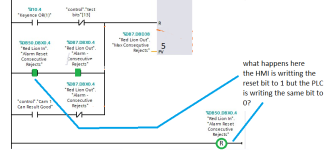
Scan 2: "What happens when here "when" the HMI is writing the reset bit to 1 but the PLC is writing the same bit to 0?"

It depends: when do those two events occur? Specifically,

  • when does the HMI write the 1 to the reset bit?
    • That presumably happens once per operator press of the alarm reset button.
    • When the bit is written in the PLC depends on the scheduling, as noted in the previous post.
    • The important thing to know is if it happens
      • before both the CTU instruction and the -]R[- instructions
      • after the CTU instruction but before the -]R[- instruction
      • after both the CTU instruction and the -]R[- instruction
      • N.B. "before both" and "after both" are essentially the same case, because another scan of OB1 will start soon after the current scan completes
  • If the HMI I/O is synchronous with this Main OB1 (or called from same) logic scan, then the 1 can be considered to be written before both instructions.
    • In that case, everything works as intended:
      • First, the CTU is processed:
        • IFF the consecutive rejects alarm is active, the CTU is reset, which clears the alarm.
        • IF that alarm is not active, the CTU is not reset, which should be okay because it means the operator pushed the alarm reset button when no alarm was active.
      • Second, the -]R[- instruction writes a 0 to the reset bit.
        • which should also be okay because
          • Either the previous instruction either cleared the alarm if the alarm was active so the reset bit is no longer needed,
          • Or it did nothing if the alarm was not active, in which case the operator should not have pressed the button in the first place.
        • In either case, the reset bit will be a one-shot i.e. true for no more than one scan.
  • If the HMI is asynchronous with the program cycle, there are two cases to consider
    • One: if the HMI writes a 1 to the reset bit after the second rung (-]R[-) and before the first rung (CTU), the logic is the same as for the synchronous case above
    • Two: if the HMI writes a 1 to the reset bit in the very brief period after the first rung (CTU) and before the second rung (-]R[-), what happens depends on the state of the alarm, which is one of two sub-cases:
      • Sub-case one - the alarm is not active: it does not matter, because when the CTU ran there was no alarm to reset and the operator should not have pressed the reset button.
        • The second rung (-]R[-) writes a 0 to the reset bit
      • Sub-case two - the alarm is active: it does matter, because in this case, the alarm was left active as the reset bit was still 0 when the CTU ran,
        • The second rung (-]R[-) writes a 0 to the reset bit
        • On the next and subsequent scans, the reset bit is 0, so the alarm is not cleared,
          • hopefully the operator eventually notices and presses the reset button again and the process starts over.
scan2.png
 
Alternate scan 2: watch several of these videos; the entire series can be viewed in 2h; watch them again until you know what Ron is going to say before he says it. Then duplicate what I did in the previous post.

The summary point is this: in ladder logic on a digital PLC, the rungs and branches, when you read them right-to-left and top-to-bottom, represent time; they do not represent current or power or voltage and the instructions do not represent relays. It may be sometimes convenient to use the latter analogy (current and relays), but you should never forget that they actually represent time.
 

Similar Topics

The new alarming functionality built into Studio 5000 is extremely useful for programming, monitoring, and keep track of alarms. The problem is. I...
Replies
1
Views
1,481
Hi all, Although I am working with my first Graphite display, this isn't my first go-around with Crimson. I started working with a few things on...
Replies
6
Views
5,103
Can you program the Help button on the Alarm Viewer to go to a different page? I want to create a separate page with the alarm details on it.
Replies
1
Views
1,222
I'm using a Graphite to add to an existing machine that has about 15 alarms set to trigger a red light. I'm wanting to use the alarm viewer as an...
Replies
1
Views
2,107
Customer is getting email alerts from a Graphite HMI and now want to be able to change the recipients' addresses at runtime. I am not sure if...
Replies
3
Views
2,636
Back
Top Bottom