DNet Scanner Mapping Question.....

JoseM

Member
Join Date
Jul 2011
Location
Texas
Posts
381
Can you guys explain to me how a 1747-SDN is mapped to work with an SLC 5/04.

On the pictures I posted, the number 1 shows the address N72:0/0 to be the "Run Forward" command to a VFD.

That VFD in question is the one that you see mapped on the RSNetworx configuration file as node # 1 on picture 2.

I'm confuse on how the memory data M0 and M1 correlates in this case to N72:0/0 which is an output to the VFD.
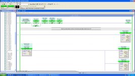
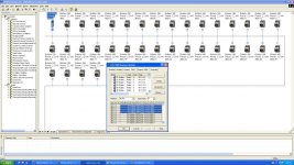
DeviceNet_Pic 1.jpg DeviceNet_Pic 2.jpg
 
I found where the "COPY" instructions is used to moved data between the SLC data registers and the 1747-SDN M0 and M1 Data tables.

Now, do I need to set the VFD parameters to tell the device when a bit value of 1, for example on M0:12.0/0 means a "Start Signal".
 
Jose,
Your second pic shows the INPUT tab of the Scanner's Scanlist memory mapping; since we are "talking" from within the PLC's vantage point, the four 16-bit words (8 Bytes) represent the data read by the SLC from the drive; usually the first word (16-bits) constitutes the STATUS of the drive (it is usually examined by the ladder logic at bit level) and the second word represents the SPEED FEEDBACK of the drive (examined at word level by the user application).
I do not know what type VFD we are looking at; it might be a device requiring 32-bit data format, in which case the first two words represent the 32-bit STATUS word and the last two the 32-bit REFERENCE or there is other data read from the drive via Data Links hence the INPUT Scanner Scanlist data slice has been increased; the VFD User Manual/DeviceNet Integration Manual should provide you with the data structure of the fieldbus communication buffer.
This really is elementary DeviceNet theory and you might want to study the Manuals links I have posted within the RSLinx SDNPT driver thread; there is a lot of information in need to be comprehended before any attempts to edit/configure a DeviceNet network should be commenced.
 
These units are 160 SSC speed drives. What is really confusing to me is how I know where the VFD data will be placed on the 1747-SDN data tables. For example which bit level on your M file should be the one to start the drive. Which one should be the one to stop the drive, etc. Which DWord is the one that is going to hold the feedback of the drive speed.
 
Last edited:
PowerFlex 40 specifically.

PS.

That last document you link has all the info I needed to see. Thanks very much.
 
Last edited:

Similar Topics

Hello everyone. Working on a small project. We are trying to use (/ get rid of) old hardware we have lying around. I am trying to get an old 2.04...
Replies
0
Views
1,447
I'm remotely connected to a customers PC right now trying to solve a problem. Earlier they thought they had a bad scanner card and replaced it...
Replies
1
Views
2,213
Hi all. I am having a bit of trouble with the above setup. I will eventually connect several drives to the DNet but as I do not have these I am...
Replies
9
Views
4,656
Hi All, I am looking for some advice regarding the correct steps that should be taken if I was to replace an existing (but now obsolete) Third...
Replies
4
Views
2,639
Hi everyone! I am newbie here so be kind) I have some m340 plcs in one network and one TSX quantum, that reads data from them via io scanning...
Replies
3
Views
1,449
Back
Top Bottom