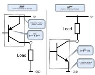
Does any relation between Sinking/Sourcing PLC inputs and NPN/PNP sensors?

From JordenCClark (the 2nd reply), "If you have a sourcing input, it's PNP. You need it's compliment to sink the current from the input: NPN"
I didn't understand that either!!:confused:
OK ...... one more time. Let's assume (since you didn't tell us) that you have a normal PLC that works with a 24vdc power supply.
If your PLC requires sourcing inputs then it is expecting to see +24vdc from your sensors for an ON condition and zero volts for off. The sensor output that does this is a PNP transistor.
If your PLC requires sinking inputs then it is expecting to see 0vdc from your sensors for an ON condition and +24 volts for off. The sensor output that does this is a NPN transistor.
The same is true for outputs.
A sourcing (PNP) output will provide +24 volts when ON. A sinking (NPN) output will provide 0 volts when ON.
 
The fact that there are NO and NC contacts has nothing to do with PNP or NPN.

You have stated that the PLC has 'sourcing' inputs. That means that one side of the internal circuitry (unless they have a weird concept of 'sourcing') has one side connected to the + side of the DC power supply and needs a connection, provided by your input device, to the - side of the DC power supply.

So you will connect the - side of the DC power supply to one of your contacts and the other side of that particular contact to the module input pin.

If you connect the NC contact the resulting bit in the input table will be TRUE until the operator activates the control at which point it will turn FALSE.

Similarly, if you connect the NO contact the resulting bit in the input table will be FALSE until the operator activates the control at which point it will turn TRUE.

It may be time to learn some electronics to help with wiring analysis.
 
Last edited:
I didn't understand that either!!:confused:
If your PLC requires sourcing inputs then it is expecting to see +24vdc from your sensors for an ON condition and zero volts for off. The sensor output that does this is a PNP transistor.
If your PLC requires sinking inputs then it is expecting to see 0vdc from your sensors for an ON condition and +24 volts for off. The sensor output that does this is a NPN transistor.
output will provide 0 volts when ON.

Mendonsy, where did you get these definitions? Was it from a particular PLC brand? If you check out Automation Direct or AB, you will see that it's the opposite of what you described. Your output definition is consistence though.
 
I think Mendonsy was responding to the posting:

Ok. I have a Sourcing Input PLC and I need to connect a palm sensor to the input

And interpreted it as the PLC 'requires' a sourcing input. (Another reason I like DIAGRAMS!). If that were the interpretation then his statements are OK.

But that's not what the poster said. The implication of 'a Sourcing Input' is that the input internally 'sources' current (in the classical current sense of 'supplying' current by being attached to the + side). Thus it requires a sinking device (or NPN if referring to a 'transistor type' device.)
 
Sinking and Sourcing Inputs and Outputs

That's correct bernie. NPN for a Sourcing input, and the "classical current sense" is how it should be read.

I think this might be getting very confusing for some here guys?

I haven't looked at the AutomationDirect explanation Tom, so forgive me if I repeat a lot of it.

This is the simplest explanation I can give as to how Sinking and Sourcing should be interpreted...

The terms Sinking and Sourcing specifically refer to the direction of the dc current, not the polarity of the voltage. I think this is where a lot of people get confused?

It is a simple dc circuit. The direction of the current is always from the +Vdc to the -Vdc. So when we say an input is Sourcing, it is Sourcing current to a field device. The field device in turn is switching that -Vdc back to the supply. This allows a current to flow from the +Vdc on the common of the input, through the input, out on the -Vdc and back to the supply. I think people mix this Sourcing up as referring to Sourcing voltage, and so think it should be +Vdc at the input? A Sourcing input is allowing current to flow in through the common +Vdc and out to the field device, so it must be a -Vdc.

However, by changing the polarity of the voltage, we can reverse the direction of the current. So if we use -Vdc at the input common, we require a +Vdc at the input terminal. This is now a Sinking current input. A +Vdc, from the supply, is wired to one side of the field device, which, when activated, switches the +Vdc to the input terminal. The current can now flow from the +Vdc of the supply, through the field device, into the input and back out on the -Vdc on the input common terminal, and back to the supply.

For either Sinking or Sourcing, an input does not care what direction the current is flowing, as long as enough current is detected to drive it high.

Likewise, an output does not care which direction the current is flowing. It merely supplies one side of the load to complete a circuit.

So for both an input, and an output, that support Sinking or Sourcing, they can pass +Vdc, or -Vdc.

Sinking and Sourcing also mean different things depending on which side you are looking from...

Field devices connected to the +Vdc of the field power supply are known as Sourcing field devices...
They are Sourcing current to a Sinking input by switching the +Vdc through themselves to the input...

So...
A Sinking input has a permanently connected -Vdc at its common. It requires a +Vdc from a Sourcing field device.

Field devices connected to the -Vdc of the field power supply are known as Sinking field devices...
They are Sinking current from a Sourcing input by switching the -Vdc from the input through themselves to the supply...

So...
A Sourcing input has a permanently connected +Vdc at its common. It requires a -Vdc from a Sinking field device.

So...

Sourcing Field Devices are used with Sinking Inputs...

The field device is on the positive side of the power supply between the supply and the input terminal. When the field device is activated, it sources current to the input circuit.

Sinking Field Devices are used with Sourcing Inputs...

The field device is on the negative side of the power supply between the supply and the input terminal. When the field device is activated, it sinks current from the input circuit.

Sourcing Field Devices are used with Sinking Outputs...

The field device is on the positive side of the power supply between the supply and the output terminal. When the output is activated, it sinks current from the field device.

Sinking Field Devices are used with Sourcing Outputs...

The field device is on the negative side of the power supply between the supply and the output terminal. When the output is activated, it sources current to the field device.

See attached diagrams...

To answer your questions...

Tofo said:
Does any relation between Sinking/Sourcing PLC inputs and NPN/PNP sensors?

Although they are widely used together, PNP and NPN sensors have no direct relation to Sinking and Sourcing input circuits. They are just a couple of the many devices you can connect to PLC inputs.

Also, just because a sensor says it is PNP or NPN, does not necessarily mean that their outputs switch positive or negative respectively. PNP and NPN merely refers to the type of transistor used inside the sensor. Positive (P-doped), and Negative (N-doped) semiconductor layers are used make up the transistor Base, Emitter and Collector. This electronic switch within the sensor does not always determine the polarity at the output. As mentioned, you can have 4 wire PNP and NPN sensors, which provide a N.O. or N.C. option. On some sensors you have to wire one of the output wires to -Vdc, or +Vdc as well to change the outputs polarity.

Tofo said:
...OK. Now I want to make sure that I understand correctly.
From what I understand from the replies, if I have a Sourcing Input PLC, I will need to connect a NPN sensor...

Your Sourcing input is Sourcing current to the Banner OTB. So a -Vdc is required between the input and the device, but the device, in this case, is not an NPN sensor.

Tofo said:
...If that is correct, will my PLC detect Hi or Low when my NPN sensor detect something?...

...should I connect the NO or NC? and why? When I choose NO or NC, do I need to consider whether the PLC input is Sinking or Sourcing??

The Banner Optical Touch Button (OTB) is a photo-electric sensor, and not a PNP or NPN sensor. It provides you with a dry Single Pole Double Throw (SPDT) relay changeover contact. Because your input is Sourcing, you must connect -Vdc to the relay contacts Common terminal (Yellow).

You have to consider the input type as that will determine whether you need +Vdc or -Vdc on the relay Common. Again, you need -Vdc for your Sourcing input.

N.O. or N.C.? - You decide whether it's "Hi or Low"...

If you want your input to only be TRUE when a finger is placed on the OTB, wire back to your input from the N.O. Contact (Black). If you want your input to be TRUE until a finger is placed on the OTB, then wire back to your input from the N.C. Contact (White).

Both contacts are switching the -Vdc from the relay Common.
Note: Wiring N.O. or N.C. does not make the Banner OTB PNP or NPN.

Just to hammer this home...

All devices that switch +Vdc to an input are not automatically called PNP, and all devices that switch -Vdc to an input are not automatically called NPN. They are only transistor types.

I Hope that's clear enough?

p.s. the OTB SPDT contact must switch a minimum dc load of 100mA. Your input may not provide a high enough load to cater for this. If not, I would suggest you drive an interposing relay from the OTB, and switch the -Vdc through that relay to your Sourcing input.

G.
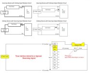
Sink_Source.jpg
 
I didn't understand that either!!:confused:
OK ...... one more time. Let's assume (since you didn't tell us) that you have a normal PLC that works with a 24vdc power supply.
If your PLC requires sourcing inputs then it is expecting to see +24vdc from your sensors for an ON condition and zero volts for off. The sensor output that does this is a PNP transistor.
If your PLC requires sinking inputs then it is expecting to see 0vdc from your sensors for an ON condition and +24 volts for off. The sensor output that does this is a NPN transistor.
The same is true for outputs.
A sourcing (PNP) output will provide +24 volts when ON. A sinking (NPN) output will provide 0 volts when ON.

Your digital Input "theory" is completely the opposite of the "mainstream" accepted one.
The digital Output is correct.
Personally, I have found it a lot easier to comprehend it when relating the digital Outputs to the digital Inputs.
A Source Output will need to be connected to a Sink Input in order to establish system functionality. -> PNP
A Sink Output's state could be examined only by a Source Input Point. -> NPN
Since a system's Inputs are fundamentally opposite to its Outputs then the sink/source atributes will have to "match" the components attached to; from a functionality theoretical point of view it doesn't really matter what type of polarity is being "switched" as long as it is being "followed" accordingly and consistently.
The polarity will need to be addressed when troubleshooting and I find a lot more less prone to "misunderstanding" to follow the arrow of the electrical diagram transistor's Emitter (either Input or Output):
Away-from-the-Gate -> PNP (PositiveNegativePositive junction)=(+) "switching"
Toward-the-Gate -> NPN (NegativePositiveNegatine junction) = (-) "switching"
 
When I was starting out in my PLC adventures a number of years ago I attended a seminar hosted by some Allen Bradley gurus. The explanation example they provided was think of it as a male female plug setup. If one end of your cord has a female end you would need the male end to hook it up and complete the circuit. Overly simplistic take on the whole debate.
 
The polarity will need to be addressed when troubleshooting and I find a lot more less prone to "misunderstanding" to follow the arrow of the electrical diagram transistor's Emitter (either Input or Output):
Away-from-the-Gate -> PNP (PositiveNegativePositive junction)=(+) "switching"
Toward-the-Gate -> NPN (NegativePositiveNegatine junction) = (-) "switching"
Sorry, bud. Your arrows are backwards.:)

Here is my somewhat simplistic diagram, complete with what makes it sourcing or sinking, and threw in a handy mnemonic for good measure!

12-11-2013 8-41-19 AM.jpg
 
Yep, I stand corrected...:D
I guess the real current flow within a DC circuit- from (-) to (+)- does not apply within the accepted conventions... it's just stuck in my head...transistors' emitters arrows (conventionally) point the opposite way the physics defined ones do...
This has been around for so long that no one really questions why, within a theoretical DC circuit, the "charge carriers" are the protons(+) and not the electrons(-) which we all know, are the true "working ants"...:unsure:
 
There are 2 kinds of I/O circuits.

1. "Sinking" aka "Allen-Bradley sourcing". Use with NPN sensors.
2. "Sourcing" aka "Allen-Bradley sinking". Use with PNP sensors.

As it has been said many times, it is better to avoid using "sink" and "source" terms altogether.
 
...if I have a Sourcing Input PLC
In language terms, that statement would not be enough to describe the circuit as Bernie said.

Does that vague statement mean that the PLC has an input terminal that will ACCEPT a Sourcing Input Device (therefore there is a Sinking Device inside the PLC), or does it mean the internal PLC input device is indeed Sourcing the current internally (therefore needs a Sinking Input External Device)? There is no way to know without more information.

Language is the real difficulty, and I see that many of you are not aware of that, so you will argue about this topic forever, just like the Upload and Download conundrum.
 

Similar Topics

I am trying to connect with a Schneider plc which has a firmware version only available in Somachine v4.2. In Machine expert After taking upload...
Replies
0
Views
112
They are installed in a control panel that was made in France and are intended for the termination of analog inputs. Each of the red capped...
Replies
4
Views
420
So, I'm really just trying to get some experience by practicing with arrays. I'm using studio 5000 v33. I have one rung with an XIC bit that's...
Replies
5
Views
233
I tried researching but I still don't quite get it. As far as I understood, it's used after a function is called in STL and then if the function...
Replies
1
Views
145
Back
Top Bottom