emergency "repair" of a DL105

awander

Member
Join Date
Jun 2012
Location
PA
Posts
6
Hi All:

I just found this site, and it seems great!

I have been tasked with coming up with a way to repair a small custom controller for one of our customers. The controller uses a Koyo DL105 to control a DC motor controller, which opens a set of millwork doors that cover a projection screen.

Everything seems to work except for the DL105. When 120VAC power is applied, no lights are lit, and there is no response to any of the dry contacts on the inputs.

I thought it might be something simple, so I opened up the DL105, and started tracing the power supply circuitry. I discovered that there is a 10 ohm resistor in series with L1 power lead, which was open. I replaced the resistor, but the unit still does not power up-I have done a little bit more circuit tracing, and it appears that here is a small analog power supply on the board-but the transformer seems to be open as well.

I am pretty much resigned to purchasing a new DL105 as well as the programming software, but since my company was not the one who originally built and programmed the controller, I am not sure how it was set up to run-and the customer is no help in this instance.

I am wondering if i can somehow try to pull the program out of this DL105. I thought of maybe disconnecting the onboard power supply(probably by pulling the regulator off the board) and applying an external 5V DC supply in it;s place(all of the chips on the board appear to be 5V supply). Then, if the program didn't get whacked by whatever took out the power supply, I thought I could save the existing program.

Does anyone have any thoughts on this?

Andy
 
Welcome to the forum!
I say it's worth a try. I would check very closely between the 5V buss and ground 1st to be sure there is not a very low resistance or short present. I would also suggest getting a strong light shining from the back side of the pc board and using a magnifying glass to inspect for cracked chips or dark spots on the pc board.
It might be simpler to just write new ladder code if you know the functions that the PLC was doing.
 
Last edited:
I'm digging a little deeper-it looks like the power supply in the DL105 is switch-mode, not analog. The thing i thought was a tiny power transformer is actually a line filter.

The circuit, as far as I have traced it, is as follows:
-AC L1 passes through a 10 ohm 2W resistor, then through one winding of the line filter, and to one "AC" terminal on a small bridge rectifier
-AC Neutral is tied to the other winding on the line filter, and passes through that to the second "AC" terminal on the bridge rectifier.

Andy
 
Hi jrwb4gbm:

Thanks for the reply. I am hoping to get the old code, only because I don;t know how they were doing it. The OPEN and CLOSE functions are activated by momentary closures, and I can't get any info from the customer on whether the motor gets activated for a certain amount of time, or if there is a limit switch that shows when the end of travel has been reached, etc....

And, of course, they want it done on a small budget, so the less engineering and troubleshooting we have to do in the field(on site) the cheaper it will be.

It sure would be nice to have a schematic diagram of the DL105, but I can imagine that would be difficult to obtain....

Andy
 
Here is a link to AutomationDirect's technical forum, maybe someone there could help provide a schematic. With current prices near $200 the people on the forum would probably say just replace it, but you never know.
Link:
http://forum.automationdirect.com/
 
While you are waiting for info, take a few minutes to list and post the known inputs and outputs and a general scope in detail of what you know about how the program works.
 
Dry Contact Inputs:
-OPEN to X0
-CLOSE to X1
-STOP to X2
-"GUARD SIGNAL" to X3 (this was labelled in the controller, but nothing was hooked up).
-"MANUAL STOP" to X4(jumpered in inactive state)
-X5, X6, X7 & X10 get wired up to "something near the motor", which is inaccessible unless they pull down the millwork. These are the biggest mystery to me.
-RESET to X11

Relay Outputs(function listed is on Motor Controller Board):
-FORWARD to Y0
-REVERSE to Y1
-STOP to Common(?)
-"FULL SPEED" to Y2(otherwise the motor turns at a slower speed)
 
I would also call tech support at Automation Direct. I'm sure they would have a way to salvage the program from it for a nominal fee. Heck, they may even do this as a courtesy if you buy a new PLC from them... :confused:

🍻

-Eric
 
Dry Contact Inputs:
-OPEN to X0
-CLOSE to X1
-STOP to X2
-"GUARD SIGNAL" to X3 (this was labelled in the controller, but nothing was hooked up).
-"MANUAL STOP" to X4(jumpered in inactive state)
-X5, X6, X7 & X10 get wired up to "something near the motor", which is inaccessible unless they pull down the millwork. These are the biggest mystery to me.
-RESET to X11

Relay Outputs(function listed is on Motor Controller Board):
-FORWARD to Y0
-REVERSE to Y1
-STOP to Common(?)
-"FULL SPEED" to Y2(otherwise the motor turns at a slower speed)
I suspect that two of the four mystery inputs, (X5,X6,X7, and X10) are stop limits for the FWD. or REV. direction. The other two could be located physically in-between the stop limits to initiate a "Goto Full Speed" feature. That would allow a slower speed as it nears the stop limit for a more precise stop position.
 
I can't get any info from the customer on whether the motor gets activated for a certain amount of time, or if there is a limit switch that shows when the end of travel has been reached, etc....
Most likely there are limit switches that stop the motor when the doors are open or closed. Using a timer is not usually very satisfactory, because slight variations can cause the doors to stop short or overtravel.

I have reverse-engineered several PLC programs. There is a pattern to follow:

(1) The place to start is to make a document search. Look for wiring diagrams, hard-copy printouts of the PLC program, and old floppy-disk or CD copies for the initial installation. Your customer should have got some of those items at one time (though many throw them away or lose them or file them where they can never be found).

(2) Look for the name of the company and the programmer that wrote the program. You might get a copy from them, if they are still in business and willing to cooperate.

(3) If you cannot find a copy of the PLC program, then download a free copy of the Automation Direct DL-105 User Manual from

http://www.automationdirect.com/adc...-a-_Modular)/DirectLogic_105_(Micro_Brick_PLC)

You can dowload the entire DL-105 User Manual, or just the Chapters that you need. You might want to first look at Chapter 2 for the specifications and wiring diagrams on the 6 different models of DL-105 to figure out which model your door opener is using. A guess would be the DL-105 model F1-130 AR with 10 AC Inputs and 8 AC Relay Outputs. Now, using the wiring diagram in your new User Manual for the specific DL-105 that you have, make a list of the Inputs by looking at the Input terminals on the PLC and seeing which ones are wired, and where the wires go to (Start/Stop switches, Open/Close pushbuttons, or travel limit switches). Then check the Output terminals for which outputs are wired and where they go. Often the wire numbers on the wires can be matched up to the final wiring desitination (open/close motor).

(4) Once you know most of the Inputs and Outputs, re-writing the program should be fairly easy for this simple open/close door opener, and you can get lots of help here.
 
Last edited:
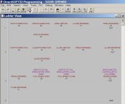
Based on your Inputs and Outputs, your DL-105 program should look like this. The X5, X6, X7, and X10 inputs could be swapped around differently, and the polarity (NO or NC) must be determined by measuring these inputs with an ohmmeter while off, or by trial and error.

Projection Screen Door Controller.jpg
 
Last edited:
@ Lancie1,
Nice job on the code. I was trying to envision that the switches for "Full Speed" might be momentary as the actuator passed by. I just couldn't quite figure the code under that concept. By using your approach, the code makes more sense.
 
Thanks. Since there is a DC motor controller, most likely it has 2 speeds, and is switching from slow to fast right after starting, then back to slow right before reaching the travel limit, going in both open and close directions. The limit switches will have to be capable of switching at the correct times, and of course which switches are used is only a guess, so I listed them in numerical order as a good first guess.
 

Similar Topics

Hi need help why this “failure 5 emergency stop “ appears at every startup in the morning ? Have to shut off main switch at least 10 times on...
Replies
19
Views
317
Hey guys. currently running an automation system that includes 60 Panasonic servo drives with STO function. Omron PLC tied into the safety system...
Replies
22
Views
1,120
Hello, I have plc Schneider TM241CE40T with the hmi HMIS5T. Do you have idea how to disable a button after an emergency stop to vijeo designer ...
Replies
5
Views
1,470
Dear colleagues I am learning to program siemens plc. I have a problem with how to solve the problem with a power outage and emergency STOP...
Replies
3
Views
1,747
Hi, I would like some recommendations/advice on wiring of a dual channel Emergency Stop for a 240V AC motor (single phase), I have 3 options in...
Replies
47
Views
13,699
Back
Top Bottom