GE Adding Math Caculation

sjohnson

Lifetime Supporting Member
Join Date
Feb 2010
Location
MI
Posts
247
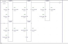
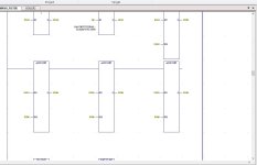
Hello, Been a while since I posted , Still sucking air been a interesting 3.5 years the dreaded health with old age scenario. Back at it and had a conversation with another and just wondering thoughts on correct of adding sum.. Granted the output calculates the same or comes up with the same conclusion but brain thought says using the same variable to sum every add would be fighting the previous equation but the output dont seem to reflect that.. just thought if one uses different SUM as in #1 or the same SUM as in #2 .. Hey glad to be back and hope all have a wonderful weekend..

1.JPG 2.JPG
 
Second picture - in order to not be confused you need a different result variable for each sum then use that as an argument for the next sum. You are seeing the sum value as it exists at the end of the scan after all the calculations.
 
Last edited:
Thanks Bernie, Unsure if your saying the same thing as in Picture #1 as i have a different variable for each sum and add each arguement which is the way ive been doing it as in my head if using same variable each expression fighting the other..
 
The sums are working properly in the second picture but the values for the results of the sums are as the variable exists after ALL the sums are done. It is therefore confusing. Using different variables for the sum results lets you see the intermediate results. The programming PC receives the values only at the end of the scan.
 
Last edited:
Thats my thoughts as well, if one looks at it at a glance how could. 4000+4000=20000 just curious how the expression isn't fighting itself but maybe it is. like maybe it's just common core math. :) thanks for your input always appreciated.
 
The sums are working correctly. The confusion comes from the communication by the programming PC. It doesn't ask for the value of the sum variable after each individual sum but only after the scan is done. The sum variable then only has one value - the final one of 20000. It thus displays that value in each of the variable positions on the display. To make it even more confusing, just for fun, repeat the use of that variable as the result of the division. It's best to use separate variables for intermediate results.
 
GE Math

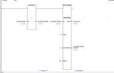
For all Practical Purposes I would do #1 Every time we have an outside source giving guidance on Boiler operation for EPA Reque. Like two Bucks in rut seem to lock horns at times. But Really on the same page. I Use this as filtering in an analog signal and all practical purpose we made a User Defined Instruction so the math wouldn't be seen or calculated for the human Eye. So, it's really irrelevant and the other way was taking up too much real-estate and easier to follow, but the length of code for all these analog signals wouldn't make sense but that's how we were doing it but this is a much easier way. just wondering if it is better the use different variables or tags in the User defined instruction or not since the values aren't displayed anyway. If I was doing it the long way ide be using different tags for simplicity and ease of use for someone to come behind and understand at a glimpse without some head scratching.

3.JPG 4.JPG
 
Programming PLCs is primarily about time: the repeating scan cycles and the order of evaluation of rungs+branches+instructions comprise the clock.

The question we tend to ask are what it is doing or why it is doing something, but with PLC a more interesting, useful and diagnostic question is when did it do something?

There is no "fighting" going on even if only one tag is used for all of the sums' results. Rather the value of that one tag is updated at different times during the sequential and separate-in-time evaluations of those instructions.

In most PLC programming software that has an online mode to monitor live values, the displayed values for the instruction parameters are usually loaded from the values of the tags sample at some specific time, probably at the end of the logic scan cycle.

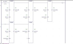
So it makes sense that, for all instances where the value of tag B2_2_LVL_SUM is displayed, the online display shows the same single final-in time value of "20000" in your 1.JPG example.

The displaying software does not care or know that the three tags around an ADD instruction were the operands to, and result from, an addition - the values of those operands and that result at the time of instruction evaluation are in the past; rather the software only knows the location of the tags on the screen and the names of the tags, and it uses those tag names to retrieve (i.e. sample at a fixed time or from a snapshot in time) the values and then write those one-time sampled values near the location of the tag.

There are some PLC programming applications (TIA Portal) that do keep track of the operands and result of an instruction from the time of its last evaluation, and ties those value to the instruction instead of to the tags. But it takes extra memory to do so, and the history of PLCs is that memory is a scarce resource, so very few applications have ever done that.
 
Coming to this late, so I don't have much to add to the discussion.

Back in the days when the number of INT addresses was limited it was fairly common practice to designate a few addresses as 'scratchpad' addresses to be used as a repository for intermediate values in extended calculations.

One point to consider in your program is whether it is possible for the individual sample values to exceed approximately 6550, making the sum greater than 32767. If that's possible you'll need to use ADD_DINT instead of ADD_INT instructions.

However... if he changes to ADD_DINT, he will have to rearrange the register numbers. A DINT will grab 2 registers.
 
As Steve mentioned, The use of scratchpad variables was common, what I used to do is first configure some temps so I could see each calc per instruction then when sure that it was working correctly just use the one if memory was tight. nowadays not a problem on many systems that have a reasonable amount of memory, I do a lot of Mitsubishi, to comply with the IEC & keep it compatible with the older ladder there are reserved areas of physical variables that are used at compile time, when using FBD often the results of more than one FBD function connected to another uses these reserved variables so for example a ADD instruction puts the result in one of the reserved variables this is then used as the input to the next maths instruction, these are not seen in FBD so no intermediate result of each function can be seen, yes a bit of a problem but then again there are always trade offs. In reality it does not matter the use of scratchpad variables either in reserved areas or put there by the programmer it still uses as many instructions in the end, I bet all FBD programming uses these local or temp variables but unlike Mitsubishi they cannot be seen.
In the case of FBD I often put each calc on a seperate rung, then when working ok I cut & paste the others onto one rung rather than leave them as seperate rungs.
 

Similar Topics

Hi Everyone, Currently we have three plants running with Controllogix PLCs (L72, L73, L74). In each of these plants we have 2 FTView SE...
Replies
0
Views
56
Hello, Im building project with 1756-L82ES controller and 1756-IB16S card but i cant find it when trying to add the card to IO configuration...
Replies
3
Views
136
Hello, I have a pair of redundant 1756-L71 controllers rev 24. These controllers currently have produced and consumed tag interfaces to 3 other...
Replies
2
Views
164
I'm adding an IAI Gateway with 2 axes connected to it. To an ethernet network on my PLC. So, I think the math is correct on the Input and Output...
Replies
0
Views
144
Hi Folks. I am gearing up to add a 2nd identical HMI to a project. This 2nd HMI will basically be an exact clone of the 1st one. The equipment...
Replies
3
Views
261
Back
Top Bottom