General doubt

advmin

Member
Join Date
Mar 2023
Location
Sheffield
Posts
59
Hello Guys,
Hope everyone is doing well.

I have a general doubt about ladder programming.

The outputs are not getting energized when I used the input contacts of the outputs and the binary bits in another program file (lad 3, lad 4...) other than lad 2.
From my quick surf through the forum, I saw something called "Last Rung Rule"

Is that what causes the restriction?
I am a beginner in the Plc, so the way scanning works is still causing confusion to me.

Please post your guidance and opinions.

cheers.


really depends on what you did with it.


if you have an input, and put it to an XIC ] [ (normally open contact), and then later put an OTE ( ) (output coil). then you won't be turning that on with anything other than the instruction that turns on the output coil.


printout what you have, or screenshot it and post it.


if this is AB, then scans from left to right, top to bottom. the last state of an output will be the state it goes to. also like mentioned earlier, if you didn't use the JSR instruction in LAD2 to call LAD3 and LAD4, then they aren't going to be scanned at all.
 
What Steve said. Did you add JSR instructions to call each routine? Failing to call a routine can cause the kind of issues you are having
 
it would help if you would attach your program (zip it first) and post it.
as mentioned, lots of possibilities.
is the plc in run mode?
is the subroutines being called that turn on your bits to the outputs?
james
 
Sorry guys for not mentioning the Plc.

PLC : Micrologix 1500.

Have you programmed calls to LAD3 and LAD4 in LAD2?
if you didn't use the JSR instruction in LAD2 to call LAD3 and LAD4, then they aren't going to be scanned at all.

Thanks for the quick reply.

I think I got the point that, to execute anything in Lad 3,Lad 4 ...., it's mandatory to use JSR for each sub-program file(in Lad 2).
Even if the input is energized, doesn't mean that we will get an output in sub-files unless we call it through JSR in Lad 2.

Could you please explain how to use the JSR function and what to care about while using it in the industry?

cheers
 
Yep, LAD2 gets scanned and if you want to go to other subroutines, you must have a JSR instruction to go to them. The scan goes to them and then comes back to your LAD2.

I generally just put all the JSR's on one rung in LAD2 but you could have condtions to go to them if you want.
 
Yep, LAD2 gets scanned and if you want to go to other subroutines, you must have a JSR instruction to go to them. The scan goes to them and then comes back to your LAD2.

I generally just put all the JSR's on one rung in LAD2 but you could have condtions to go to them if you want.

This ^^^^

JSR come from original text programming where a subroutine was short and concise and only needed to be used in certain situations.... in PLC logic, the scans are fast enough and the code is minimal that there's no need to split things off and make these 'Jumps' based on special conditions unless the program is large enough to warrant it.

Most of the time unless you're working with a big complex program, just put a JSR to each Ladder in the main ladder with nothing in front of it and you'll be fine.


If you imagine a scan reading top to bottom.

you have 3 rungs, in LAD2, and those 3 rungs each have a JSR.

JSR LAD3
JSR LAD4
JSR LAD5

When it comes to LAD2 and reads the first rung, it jumps to LAD3, then continues down dealing with any and all logic in there, when it reaches the end of that LAD3 subroutine, the END instruction at the last rung will send it back to where it came from one rung down.

So it then Scans rung 2 in LAD2 and sees JSR LAD4 and then Jumps to Subroutine 4, and scans that top to bottom, til it gets to the END.

and on and on. You can get more complex but that's the basics of it.
 
Last edited:
Thank you guys for your valuable feedbacks.
I understood the concept well and will implement it in my program soon.
Will get back to you if I am stuck on it further.

thanks again and have a great weekend
 
Hello guys,

plc : ML 1500
soft : RsLogix 500

As per your suggestions, I have used the JSR to call a sub-routine file and it went well so far. But now I countered an issue with one of the outputs.
I have attached the zip file along with this post.

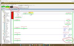
The output o:0/4 is in subroutine files 4 and 5. Both are called in lad 2.
This output is not getting energized at sub-file 4 even when the input is energized. But
It's getting energized on subfile 5.
All other similar outputs are getting energized in both sub-files.

When I removed this output from subfile 5 and ran the program, the same output at subfile 4 gets energized.

Why the output at subfile 4 is getting energized when I removed the same from 5?

cheers.

plc talk 1.jpg plc talk2.jpg
 

Attachments

  • REV 7 - plc.zip
    14.7 KB · Views: 3
Generally speaking, its bad practice to have the same output used more than once in the program. I didn't look at your program but are you calling Lad4 and Lad5 each scan without conditions? If so, which one is to control O:7/4? One sub may turn it ON and the other sub turn it OFF, all within the same scan. One Sub will win out and you may not get the results you expect, as you have seen. Not good.
 
If you want to have multiple different things run the same output, then Map the output in one location and have each area able to activate it depending on it's own independent output.


]X1[ -------------(O1)
]X2[ __|
]X3[ __|


Sub4-

]X4[ ---------------(X1)

Sub5-

]X5[ ---------------(X2)

Sub6-

]X6[ ---------------(X3)


In this way each individual subroutine can use that output, independently of the others.

if you just put (O1) in all the subroutines, then the last one scanned will be the state of it during the operation. So if the last one is not energized, Output 1 will be Off regardless of the other subroutines before it.
 
Generally speaking, its bad practice to have the same output used more than once in the program. I didn't look at your program but are you calling Lad4 and Lad5 each scan without conditions? If so, which one is to control O:7/4? One sub may turn it ON and the other sub turn it OFF, all within the same scan. One Sub will win out and you may not get the results you expect, as you have seen. Not good.

^^^YES!

I had this occur on one of my first machine programs also using a ML1500. I learned that it helps to use a subroutine as an I/O map and use internal bits throughout the rest of the program to represent the physical inputs and outputs. In the I/O map those internal bits will trigger the physical I/O with each point only being used once. Typically an input will trigger a signal internal bit, but outputs will sometime be triggered by multiple bits.


-----] [---------------( )
I:0/0..............B3:0/0
-----] [---------------( )
B3:1/0.............O:0/0
 
That's brilliant guys.
Now I completely understood the logic behind this concept.
I have read a bunch of things to understand this concept, but it's you guys provided the best and most detailed information on this one.
Now my program is running well.

Generally speaking, its bad practice to have the same output used more than once in the program
Yes, I will definitely keep this in my mind while doing the program .

f you just put (O1) in all the subroutines, then the last one scanned will be the state of it during the operation. So if the last one is not energized, Output 1 will be Off regardless of the other subroutines before it.

Thanks for the detailed reply. Really helped me

In the I/O map those internal bits will trigger the physical I/O with each point only being used once. Typically an input will trigger a signal internal bit, but outputs will sometime be triggered by multiple bits.

Thankyou Mueller. I followed the same steps as you pointed out and illustrated here.


cheers all.
 

Similar Topics

What is your perspective? Are you a Maintenance Tech? Systems Integrator? OEM Engineer? What are your thoughts on the topic of source...
Replies
24
Views
1,168
Wizards, It has been a few, but you all have always done me well. I have acquired a 1769-L33ER and want to use it as my collection PLC to...
Replies
5
Views
520
Hi! I recently discovered how to get to configuration mode and disable printing for connecting to PanelBuilder32 and updating my Panelview...
Replies
1
Views
451
Hey all, I'm teaching myself PLC programming, and don't have a lot of resources at my disposal, so probably a very basic question, but I recently...
Replies
9
Views
2,404
Can anyone suggest any insurance companies familiar with our field (PLC programming and controls hardware design) that can provide general...
Replies
10
Views
1,800
Back
Top Bottom