help to convert stl to Lad

hamedkhatab

Member
Join Date
Jan 2023
Location
egypt
Posts
2
i hope you could help me to convert the network Stl to lad
it's apart from program of machine
and i try to find solution for the reason of error

AN I 126.3
A I 126.4
AN I 126.5
A I 125.5
A I 125.3
AN M 90.0
= M 90.3
A M 90.3
L S5T#2S
SD T 1
A I 126.5
A M 90.0
S M 90.1
AN M 90.0
R M 90.1
A M 90.1
A(
O I 126.3
ON I 126.3
)
= M 90.2
A(
O T 1
O M 90.0
)
AN M 90.2
A I 125.5
AN I 126.5
AN I 126.3
= M 90.0
 
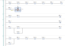
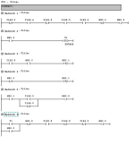
Here you go, however, I do not have S7 installed on this computer so did it in another platform but this is how the logic is in ladder, it is not convertable directly I don't think (You could try selecting to view in FBD but don't think it will convert, alternativley, if you put a segment end (BLD255 I think) after the coils then it should display in ladder, this is poor programming as some logic looks like it has been quickly modified i.e. the OR of a N/O & N/C in ladder 5 it might as well not be there. Note: That I have had to create the symbols as the format is different i.e. my IDE does not allow "." so replaced with "_".
Aghh.. Aussie beat me to it

STL Conversion.png
 
It depends on many factors, the first is if the logic i.e. brackets have been put in place correctly, also there is the possibility that it was programmed in FBD (it normally requires certain instructions i.e. BLD(0-255) depending on what the format is these instructions are effectively NOP's in the PLC but tell the S7 editor how to display it. You could try selecting display in FBD on the menu to see if it will convert but I doubt it, look at the blocks it should say what language it was programmed in i.e. STL LAD or FBD.
One thing you could do is after any output coil add BLD255 this is a segment end also do the same after the call for the timer, however, I believe the timer in this case is FBD so may not convert in the same way. Also adding the segment dividers will make your logic different to the PLC you uploaded it from, this does not mean the logic is not the same but as adding in the segment end (diplayed as ***) means that it will produce errors when compared, downloading it again would re-sync the code but if you make a mistake then it could cause problems.
So in effect after each output coil (or multiple output coils) you add a BLD255 this will then translate into ladder for most code but you will not have it synced with the PLC so probably not be able to go on-line to monitor.
If you do this make a backup file to play with to see if you can get at lest some of it in ladder just for looking at.
for example
A Ixxx is as it looks needs to be true (Rung 5)
A( AND open brackets means that instructions within the brackets is anded with the "A Ixxx"
O Ixxx OR
O I xxx OR
)


The same goes for O() Sort of OR load
perhaps post the code someone may be able to convert at least some of it to ladder or if applicable FBD.
 
thanks So much
is there away to convert other Stl ?
stil beginner in STL
and i have more networks to solve

In Step7 Simatic Manager, Place cursor on the rung/network and press Ctrl+1 for Ladder (I think). Off the top of my head I think Ctrl+2 was for STL and Strl+3 was for FBD representation.

However I don't think it will convert judging by how the logic's written on your end.
 
In my experience with Simatic Manager, you would have to break up the STL network into a bunch of individual networks for it to convert to LAD. Basically, break it up after the output instructions (S, R, =, SD, etc.). When I got into some deep messes to sort out, I would do that in an offline project to avoid making changes to the running PLC until I knew exactly what was going on.


The fact that they were documented in German with shorthand and abbreviations didn't really help much either...
 
Yes as I posted, you need to insert the segment ends after an out instruction i.e. = M90.0 , S M90.0, R M90.0 or timers SD Txx
The segment end is BLD255 (well is in S5 so probably the same) once inserted & accepted it will display it as *** & then you will have ladder providing the logic is to the required standard i.e. correct bracketed branches.

Although you can omit the A( & O( in some situations it will not convert even though the logic works.


Sorry, I never saw a "***" or BLD255 in an S7 project, so I just shared what I knew to do to make it work. Just inserting BLD255 would have been simpler than what I ended up doing...
 
VAR
// Variabili di stato
Stato: INT := 0; // Stato attuale del sistema

// Variabili di controllo
Avvia_Ciclo_Auto: BOOL := FALSE; // Segnale per avviare il ciclo automatico
Taglio_Manuale: BOOL := FALSE; // Segnale per attivare il taglio manuale

// Variabili di rilevamento
Reggia_Presente: BOOL := FALSE; // Segnale di rilevamento reggia

// Altre variabili necessarie

END_VAR

// Ciclo principale
CASE Stato OF
0: // Stato di Inizializzazione
IF Avvia_Ciclo_Auto THEN
Stato := 1; // Passa allo stato di attesa reggia
ELSEIF Taglio_Manuale THEN
Stato := 5; // Passa allo stato manuale
END_IF
1: // Stato di Attesa Reggia
// Controlla se la reggia è presente
IF Reggia_Presente THEN
Stato := 2; // Passa allo stato di scansione
END_IF
2: // Stato di Scansione
// Muove l'asse Y alla posizione di scansione
// Completa la scansione
Stato := 3; // Passa allo stato di taglio
3: // Stato di Taglio
// Muove l'asse X lungo la lunghezza del coil
// Attiva il taglio
// Torna allo stato di attesa reggia
Stato := 1;
5: // Stato Manuale
// Controllo manuale degli assi e del taglio
// Possibile implementazione per il controllo manuale
ELSE
// Gestione degli altri stati o eventuali errori
END_CASE
 

Similar Topics

Hello everyone, I am migrating a program from STL to SCL via S7-1200 portal, I would like you to help me by converting these lines of code...
Replies
4
Views
1,637
I need some assistance to any Siemens Gurus' who can help me convert the following from STL to Lad. I have tried all the old tricks I can...
Replies
4
Views
4,306
V
I have no software to programming. My PLC rack contains CPU200H/SP001/OC225/OC225/OC225/OC225/ID212/ID212/ID212/.I have a console programming and...
Replies
14
Views
11,404
Hi All i was wondering if any one would be able to help me. My version of studio5000 only allows ladder and FB. i have an AOI written in structure...
Replies
2
Views
1,539
Can someone please help me out and print this entire program to a PDF. Tried to zip and upload but too big so Google drive Link below to the adc...
Replies
2
Views
1,252
Back
Top Bottom