Help with difficult school project

sparkie

Lifetime Supporting Member
Join Date
Nov 2014
Location
KS
Posts
1,148
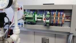
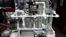
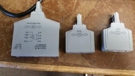
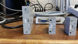
So I want to write a plc program to control this water flow process system. I'm having issue with these parts, and a hard time finding data about them without paying. They have to do with analog signals and are transducers of sorts but I'm not sure how they work, as I want to control the system with my own instructions. Can anyone give me more info on what they do or how they work?
20150224_093023.jpg 20150224_093004.jpg 20150224_092947.jpg 20150224_092939.jpg
 
I would start by determining what you want to do. Create a flow chart of the process. The analog signals coming should then be apparent on what is required.

Regards,
Garry
http://www.accautomation.ca

Thanks for the information. This equipment was here when the current instructor took the program over, but there isn't much information on it. We know "what" it does but I'm currently mapping out the wiring and terminal blocks for the system, of course I ran into those three components above and trying to find out more about them and what exactly it is they do in the system. I was hoping someone here may have seen them before. If not I can get on the phone with Festo support and figure it out tomorrow.

Also do you guys have a 15 pin digital IO plug to 15 pin serial adapter? I can get pics of the two plugs if you need. I can get my instructor to order, of course from your site.
 
This symbol [I/U] on the front of the device labeled A2 in the second picture indicates it is a current to voltage converter. Probably 20mA to 10V. The symbol with the funny character that looks like a malformed J, [J/U] on the device labeled A3 indicates that it is a resistive temperature sensor to voltage converter, most likely an RTD used to measure temperature (if I knew how to type the actual character in the symbol I would use it, hopefully the description makes enough sense).

I can't help you with device A1, the picture isn't clear enough. Those are WAGO components, you should be able to find the manuals online.

Thank you so much, now I have a better idea of what I'm feeling with. Now I need to see how these devices interact with the system, if I'm getting a scaled output or if they are intended to actually perform a task such as own a valve or control the heat for the temperature sensor.
 

Similar Topics

Hello, I need to write the following program in Ladder language, but I could not integrate the Fibonacci sequence into the ladder. Can you help...
Replies
2
Views
48
this a program to send data to barcode printer I want to integrate a new printer in a new machine and i wanted to adapt the old prgram on it but I...
Replies
4
Views
132
So i've been at this for a long while, i have Citect Scada 2018, i have full access to everything but i can't seem to find any option or...
Replies
0
Views
52
Hi all, hope you are having a great day, I am in need of your help to create a AOI or program that does this kind of job: I have a IO Link...
Replies
24
Views
439
please help me . I have to make this ladder diagram and I can’t figure it out :(
Replies
12
Views
360
Back
Top Bottom