Help with STL in Siemens Step 7 Classic... with video and attachment.

AutomationTechBrian

Lifetime Supporting Member
Join Date
Jul 2013
Location
St. Cloud, MN
Posts
669
I really struggle with STL in Siemens Step 7 Classic. I'll learn chunks, but then I don't use it enough to retain and build on the knowledge. When troubleshooting, I can usually limp through an issue with my basic knowledge, but today it's different. There is an output that is pulsing on and off, and that pulsing is beating up the components of the machine. The plant manager wants me to eliminate the pulsing. I suspect there is a timer involved, but this STL network is long, and it's taking me far to long to pick it apart. I would need a remedial class just for this one problem. I tried changing the program to LAD by View -> LAD, or CTL + 1, but nothing changes... The menu says LAD, but the program displays the same STL as it does when the menu says STL.

So I've gotten creative in capturing the issue to share in hopes that someone can give me some insight to where to look to manipulate or eliminate the pulse. If you're really bored, this might be fun. And maybe I, and a few others, might learn something valuable from this.

Here is the video of the pulsing coil. Notice the role of M37.4: https://youtu.be/aqqQWAlCoWM

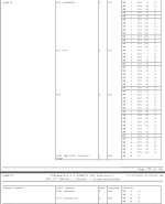
I've attached a PDF of that long network that writes to M37.4. It's so long that a screen capture wouldn't work... It's 4 pages, with very little documentation. I'm curious to see where this goes.
 
This is not translatable into ladder because of a number of factors, there are no segment breaks between what would be the networks i.e. a network for example be
L DBxx.DBWxx
L DBxx.DBWxx
=I
S Mxx.xx
*** Segment end.
Without some form of segment ends it will not translate, sorry I'm a little rusty on S7, cut my teeth on S5, in that you could not use ladder in FC's but I know that changed in S7, not sure about jumps across segments but If I remember you can, lost a few brain cells since then, there are a number of guys here that use it all the time so they should be able to help.
You really need to post the bit of code for the output for example is there a flag used in this block causing that output to switch.
 
A hack fix: put a 100ms or 250ms debounce on (M37.4 OR M94.1), assuming that is safe to do.

STL is not summat I have ever played with seriously, but looking at the PDF, I think this everything that is controlling M37.4:

L "DB60".D_11 ### Load DB60.D_11 to ACC1
L MW 82 ### Shift ACC1 (DB50.D_11) to ACC2, Load MW82 in ACC1?
>I ### if DB60.D_11 > MW82 ...
A M 37.2 ### ... and M37.2 (is 1?) ...
= M 37.4 ### ... then M37.4 is 1


I.e.
Code:
  M37.4 := (DB60.D_11 > MW82) AND M37.2;
or
Code:
    _________    M37.2  M37.4     
---[ >       ]----] [----( )--
   [DB60.D_11]
   [MW82     ]
    ---------

assuming I am interpreting the STL correctly, which it not at all certain.

So would it be useful to trend DB60.D_11, MW82, and M37.2?


We don't know where MW82 is assigned, but in that STL it seems to always be Loaded after, and compared to, DB60.D_11.
 
I suggest you try & find where DB60 DBW22 & MW82 are set it appears from the short video that it is switching quite fast also look at M92.1 if this is set then this will jump to the reset of M37.1.
It is also noticed that some of the positions are set in the DW of the DB is one of those been set to zero or a very low value ?.
Also look at the others by that I mean the timers are driven off DW in DB60 where are these set ? on an HMI or perhaps they are fixed values in the DB.
 
In the video, it appears that M37.4 becomes 1 for about 2s, then returns to 0, then has three short blips to 1 again over the next few seconds, then a single blip by M94.1.

Is it possible that there is a bit of noise in DB60.D_11 and/or MW82, e.g. if either is an analog measurement, so that [>I] comparison triggers a few times on the transition from True to False? Modifying that knife-edge [>I] comparison to be a Start/Stop Circuit pattern would put some hysteresis into the comparison, and might eliminate the noise?
Code:
[SIZE=2][FONT=Courier New]      _________        __________   M37.2  M37.4     
--+--[ >       ]--+---[>         ]---] [----( )--
  |  [DB60.D_11]  |   [DB60.D_11 ]
  |  [MW82     ]  |   [[COLOR=Blue][B](MW82-EPS)[/B][/COLOR]]
  |   ---------   |    ----------
  |               |
  |    M37.4      |
  +-----] [-------+[/FONT][/SIZE]
Where (MW82-EPS) would be the value, in some unused MWxx location, that would be a number some small epsilon less than the value in MW82. This is basically the same idea as putting a debounce on M37.4: the epsilon approach above applies a hysteresis in some process process metric; a debounce would apply a hysteresis in time.
 
Last edited:
I forgot to add, if this is an upload from the PLC the data blocks will loose their formatting, for example they can be formatted as follows
KF integer
KG float (2 DW)
KS ASCII
KH Hex
KT timer value cannot remember the timer format but it will be something like KT10.2 i.e. the 10 is the duration & 2 is the time base, as yours seems to be an upload (or someone has overitten the DB on disk) the format will be lost) so will probably be in KH, if so, on disk change those to KT I think it will go back to the correct format, perhaps someone else will correct me if I'm wrong it's been a few years since I did S7.
 
I have an 18 second video of watching addresses:

DB60 D_11: Decimal value is static... 1020.
MW 82: Starts at 75 and increases. When it goes higher than 1020 (decimal), M37.4 turns off. The value comes down after hitting a high of about 1030 (decimal), and when it goes below 1020, M37.4 pulses on again.

I'll look at the current posts and see what else you've written. I'd like to find the source of D_11... it that is a setting from the HMI, or a static setting in the DB. At some point I'll post the video on YouTube.
 
Just a thought, I might be thinking of S5 timers, perhaps S7 uses the newer IEC format i.e. T#10s this format would be in ms (10000) although I think the min timebase is 100ms so would count in 100ms seps.
 
Ok, here is the video of the watch table for those values: https://youtu.be/DlMCKRPuLYY

I slowed it way down and looped it twice through the same cycle to make it easier to see the changing values, and how they compare to 1020.

I believe this part of the program was converted to Step 7 from an older Step 5 file.
 
Just a thought, I might be thinking of S5 timers, perhaps S7 uses the newer IEC format i.e. T#10s this format would be in ms (10000) although I think the min timebase is 100ms so would count in 100ms seps.

I don't understand why the value starts at 78ish, goes up past 1020, and then decreases around 1040ish, only to go up and down a couple of times. It behaves more like an encoder value then a timer, but there isn't an encoder in that part of the machine.
 
Ah, in that case the (not-)stop condition would be
(DB60.D_11+EPS) > MW82
So if MW82 had say couple counts of noise, and EPS(ilon) were 2, then M37.4 would stay on until MW82 dropped to 1018 (= 1020 - EPS = 1020 - 2), the idea being that once MW82 drops from 1030 to 1018, it is on the way down and there is unlikely to be enough noise for a transient bump it back above 1020, so M37.4 would not experience a transient re-trigger.
 
It's not noise; this appears to be bang-bang control. When M37.4 is 1, MW82 climbs very quickly; but when M37.4 is 0, MW82 drops slowly. I am not sure, but it appears that, once MW82 has reached 1020 after its long climb from ~80, it will not be long until M37.2 becomes 0 (presumably from some other logic - I see two [R M 37.2] instruction in the STL), which will keep M37.4 at 0 and MW82 will drop back to ~80.

Here is the question: is it okay for M37.4 to remain 0 once MW82 climbs from a value of ~80 to a value of 1020, until M37.2 becomes 0 as well, even if MW82 drops (slowly) and stays below 1020 until M37.2 becomes 0?

To be honest, we don't really know enough about the process to advise usefully.
 
Last edited:
I would look at all instances of MW82 it sounds like it's counting up but then something is setting it below 1020 it does not appear to be written to in FC6 so it must be somewhere else.
 

Similar Topics

Hello, I am working on a project to upgrade some old S5-100U processors. The programs are all uploaded and I don't have descriptors...ugh. Be that...
Replies
4
Views
1,173
I need some assistance to any Siemens Gurus' who can help me convert the following from STL to Lad. I have tried all the old tricks I can...
Replies
4
Views
4,309
Hello all. I am a newbie when it comes to Siemens and I have looked in the STL programming help but there are some things that isn't explained...
Replies
11
Views
3,036
Hi All, I am a ladder programmer but I have to reverse engineer some STL code. I can't figure out this part. Can anyone help me translate this...
Replies
5
Views
1,670
Hi, I have been given the task of implementing some limited changes to an existing Siemens S7-300 application. The program was created around...
Replies
16
Views
19,223
Back
Top Bottom