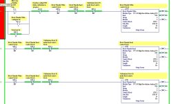
Logic for 1771-NIV/A

jwardla

Member
Join Date
Nov 2003
Posts
2
I am trying to set up a 4-20 input (conv to 1-5vdc) when I look at the data it displays a -5494. What am I doing wrong. I used the insert logic feature. Calibration maybe?

1771 niv_a_logic_3.jpg
 
4-20 input

Please forgive me if you have already tried this. Have you tried swapping your + and - wires and see what your input does then.

If you have, let me know and then I will look at some old logic that I have to see if I can find something that might need to be changed in the parameters.
 
I'm not familiar with that module, so I'm talking out of my backside on this one, but:

1. Are there configuration jumpers on the module?
2. Are there configuration bits in the I/O table of your program? The analog module for the SLC platform (1746-NI4???) needs to be configured by setting I/O bits.
3. Is the module TRULY 4-20ma or does it read a slightly wider range? I had a scaling issue once because the module was really scaled 0-21ma.

Even if you've missed one of these, I can't really imagine why you'd be seeing a negative value (unless your transmitter isn't transmitting, or the module isn't receiving). But, sometimes strange things DO happen.

If all else fails... jiggle the handle.

AK
 
Are you sure you are getting the analog input from the field device?

I would verify this with a meter or use a simulator to input known 4-20ma signal (or 1-5vdc). This will let you know if problem is in program or source.
 
I think Mark's first comment has some validity.
In my experience the 1771-NIV comes configured out of the box +/-32767 for a bipolar full scale input. If you don't explicitly change this with the appropriate field set to a non-zero value in the configuration BTR that is what you get. I also know that the 4-20mA input is not a power sourcing style input. If the 4-20mA transmitter you are dealing with is a 2-wire as opposed to a 4-wire device, you need to provide a supply from something other than the input module. So the 4-20mA input is polarity sensitive. The direction of current flow through the module will determine the sign of the input.

Keith
 

Similar Topics

Hello, I am going over some old code from days gone by. I would like the expert to confirm my findings to see if I got it correct. 1. B64:22/3...
Replies
7
Views
417
Hello, I´m having a problem trying to program in Ladder. An output should be trigged by two possible contacts. Take a look on the printscreen...
Replies
5
Views
165
I got my PanelView Plus 7 working with a Micrologix 1500. How would I connect my laptop to the PanelView to view the ladder logic while operating...
Replies
6
Views
190
Hello, I am trying to replicate a piece of logic on the PLC5 onto an SEL RTAC. I am using ladder on SEL and FBD. I am having issue on the ladder...
Replies
13
Views
284
Hello again..trying something on an existing poorly written program and just wanted to double check something system is an A-B MicroLogix 1200 In...
Replies
5
Views
196
Back
Top Bottom