Logix OSR problem

dalporto

Lifetime Supporting Member
Join Date
Jun 2021
Location
Montreal, QC
Posts
258
Hi all.

Simple as simple can be, I don't understand what's happening.

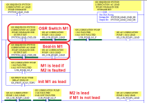
I'm toggling he OSR on, GX_LUB_PUMP1_LEAD should switch. It doesn't.

The opposite is working.

GX_LUB_PUMP_LEAD is not written anywhere else, and I removed all logic for GX_LUB_PUMP2_LEAD to make sure it's not a scanning order problem. No pending edits.

I put a TOF instead of the OSR and I see both XIC green while the latch stays off.

It's Friday, maybe I'm too tired.

Or it's a bug.

Any idea?


1712341488470.png
 
Follow the sequence.
Rung 1) GX_SEQ_SWITCH_AC_LUB_LEAD_PUMP_CMD turns on. That turns on GX_SEQ..._SB and GX_SEQ..._OB. Note that _OB will be on for one scan, but that's not super relevant for this analysis.
Rung 2) Middle branch: GX_SEQ..._OB is true. GX_LUB_PUMP2_LEAD is also true, so the middle branch is true, so GX_LUB_PUMP1_LEAD is Latched on.
Rung 3) Second branch: GX_SEQ..._OB is still true, GX_LUB_PUMP1_LEAD was just latched on in the rung above, so the branch is true, which Unlatches GX_LUB_PUMP1_LEAD.
 
Are you trying to toggle* the lead state on each rising edge of the command bit?

* transition either from 1 to 0, or from 0 to 1
 
Are you trying to toggle* the lead state on each rising edge of the command bit?

* transition either from 1 to 0, or from 0 to 1

Yeah, only on the rising edge, this comes from a SFC step.

But Joseph was right, I didn't pay enough attention that the rising edge would be true for the other rung too. I usually use it with Schneider in FBD, and anyway I would have used a SR or a RS block.

It's fixed now.
 
Yeah, only on the rising edge, this comes from a SFC step.

But Joseph was right, I didn't pay enough attention that the rising edge would be true for the other rung too. I usually use it with Schneider in FBD, and anyway I would have used a SR or a RS block.

It's fixed now.
In the downloads section of this website, under Allen-Bradley, there is a document with a name summat like "Alternators.PDF" that has many ways to skin the cat named "toggle bit."

My personal favorite is the XOR, because it combines the canonical and easily recognized Start/Stop Circuit and State Coil/Fault Coil patterns; it has a correct version of the approach you were attempting. I find latch/unlatch to be an anti-pattern here, but you could choose the one that makes the most sense to you.

Also, I assume at some point you have XIO GX_LUBE_PUMP1_LEAD OTE GX_LUBE_PUMP2_LEAD after the code above; note that you could have muted the XIC one-shot bit with XIO GX_LUBE_PUMP2_LEAD on that last rung.
I'm gonna sure check it on Monday.

Yes, I removed everything for the test, when Pump 1 is lead, Pump 2 is lag and backward, all used in logic to start the correct lead pump, and lag if needed.

It's the first one I did (I'll have at least another scheme like that later), but what I'm doing is logic to ultimately latch (needs to be latched) an AC pump output ON (from SFC Logic) later on using Set / Reset logic, with priority over the set or the reset depending of the needs. I figured out (Schneider has SR and RS blocks so it's usually a no-brainer for me) that to prioritize one over the other I need to either place the (U) or the (L) last. So right now it's working as intended, but if I can make it a notch better or easier that would be great.

On this particular logic, which are pumps for bearing cooling, which is critical that we always have one pump running, I also have a backup DC pump on the inverter that is fed from a 125DC battery bank in case we lose the 125kV line going in the station (and then the 600VAC station service MCC). What is messed up and I never saw before is that the "start" output is always on, and I need to pulse it to "0" in order to start the pump. It's like a kind of weird fail safe I never saw before. All of my 125/24DC control is already from the battery bank anyway, so it would start the pump mostly only on a 24DC PLC output relay fail, and I'll probably trip the unit on an over pressure right after that since that pump is too powerful. And then I have a stop output on that pump too, no DWG, so I don't know who wins when both commands are "ON" at the same time. Anyway I'll be already tripped and stopping by then, but it's weird.

I'm thinking out loud, sorry.

Sorry for the bad English too, still french.

Have a good weekend guys,.
 
It's your system so you should know better than anyone how to protect the bearing, but this is how I would fly:
  • one lube/cooling pump must always be lead;
  • faulting one pump always makes the other pump be lead
    • both pumps should never be faulted!
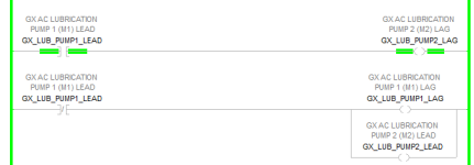
  • M1 defaults to lead if GX_FIRST_SCAN_TDPU is 1
I assume there is other logic protecting the bearing, e.g that does not let the shaft turn in the bearing until/unless there is pressure in the lubrication system, and there are two pressure switches that must both indicate pressure, in case one pressure switch fails high, etc.

Untitled.png
 
Yes, you are correct.

What I showed is only the lead / lag logic of the 2 AC pumps.

From your sketch, I'm wondering if it would have a selected lead pump if both pumps are faulted. I know that if both are faulted they won't start anyway, but still. I also want to make sure that pumps won't cycle if they go quickly into fail conditions and recover.

Just for the story, before to start I need to have both AC pumps and DC pump in auto, ready and not failed. I need all these conditions to start (customer request, I'd be comfortable with an AC and the DC).

Then I have indeed two(2) pressure switches (low and high) and possibly two (2) low flow switches (under RFI, DWG are sketchy) to do logic (from a SFC) to start the lag pump when needed, then to start the DC if it's still not working and trip the unit.

I need to talk with my automation engineer, I don't think it's a good idea to permit to switch the Lead pump while running, I'd just start the Lag pump according to the SFC and pop the alarm that the Lube is running with the Lag on (and whatever alarm from the pump that failed, like overload). That failure condition should only be there to prevent the automatic switch (that happens after the unit is stopped) to select a faulted pump as a lead. And anyway, like I said, I cannot now start with a faulted pump.
 
Yes, both your code and my code do not have either pump as lead if both motors are faulted.

You can prevent the lead-lag switch while running by adding an XIO running to the rung with the OSR; maybe even drive a TON with the XIO running and put an XIC with that TON's .DN on the rung with the OSR, so you cannot switch until the system has been not running for an extended time.

The scary part is if the lead pump's motor faults: the lag pump should become lead pump, but will its motor come up to speed and the pump make pressure before the bearing is ruined? Is there an expansion tank to maintain lube pressure over the the time it takes the system to stop safely?
 
Oh, I see, you are saying Lead and Lag designation does not change if lube is lost, but the lost lube detection* simply turns on the Lag and activates an alarm i.e. that there is no more backup. Yeah, that seems like a better approach, but you still have the issue of whether the lag lube comes up to pressure/flow quickly enough.

* low lube pressure, or low lube flow or lead pump's motor faults
 
There is a missing part I didn't show where there is always a designated Lead:

1712414580573.png


If the lead fails to keep pressure or flow (tdpu: 2s). or if there is a failure on the lead pump (meaning I'm getting the fail from the MCC bucket) I'm gonna start the Lag pump, but won't stop the lead, so no, i don't want to switch the lead status then. We won't be going on and off with the pumps, once the lag is started I run it along the lead even if the pressure and flow recovers.

If I'm still getting low pressure or flow while running the lag too, I add up the DC Pump and trip the unit. What is probably happening there is that MCC lost power, so I'm bringing the unit home on the battery bank.
 
Last edited:
Oh, I see, you are saying Lead and Lag designation does not change if lube is lost, but the lost lube detection* simply turns on the Lag and activates an alarm i.e. that there is no more backup. Yeah, that seems like a better approach, but you still have the issue of whether the lag lube comes up to pressure/flow quickly enough.

* low lube pressure, or low lube flow or lead pump's motor faults

Yes, exactly.
 

Similar Topics

Hi, What would stop an OSR from outputting? I had the attached program running for weeks without a problem, now the OSR won't output when the rung...
Replies
4
Views
1,674
So I have micrologix 1100 program that controls sonic welding system. The ladder logic currently sents output to welder to allow cycle to start...
Replies
5
Views
3,421
Is it possible to use the OSR instruction with a micrologix 1200? I am trying and getting "rung 1 ins 7: invalid output instruction position!" It...
Replies
1
Views
2,861
Hi, I am reviewing somebody else's logic and I find the following: |----(some logic)----[OSR StorageBit OutputBit]-----| |----[XIC...
Replies
2
Views
3,646
I was looking through code yesterday and found where someone used a OSR to initiate alarm notification. However... the OSR occurs in a routine...
Replies
4
Views
5,421
Back
Top Bottom