Logix OSR problem

But basically the lead / lag switch from the pump failure is moot now that we have to have all pumps healthy as a start permissive.

Also, some customers prefers to "overuse" one pump so when it fails and needs to rewind the motor or else they still have a "fresh" one. Or a gripped one...

But like it is, they cannot run the unit with a failed AC pump if they don't bypass it in the PLC.
 
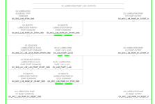
There is a missing part I didn't show where there is always a designated Lead:

View attachment 69277

...

That approach always bugs me: there is only one lead and only two pumps, so only one bit is needed to model what is going on.

I.e. if PUMP1_IS_LEAD (or whatever you call it) value is 1, then pump 1 is lead and pump 2 is lag; if PUMP1_IS_LEAD value is 0, then pump 2 is lag and pump 1 is lead. Housekeeping of another three bits (PUMP2_IS_LEAD, PUMP1/2_IS_LAG) only reduces clarity, IMNSHO.

I mean, I get it that there is a bit that has a value of 1 for every test, and that makes other code more readable, but the extra tap dancing to keep them consistent is not worth it, again IMNSHO.
 
But basically the lead / lag switch from the pump failure is moot now that we have to have all pumps healthy as a start permissive.

Also, some customers prefers to "overuse" one pump so when it fails and needs to rewind the motor or else they still have a "fresh" one. Or a gripped one...

But like it is, they cannot run the unit with a failed AC pump if they don't bypass it in the PLC.

Is this one of those "million dollar bearings?"
 
That approach always bugs me: there is only one lead and only two pumps, so only one bit is needed to model what is going on.

I.e. if PUMP1_IS_LEAD (or whatever you call it) value is 1, then pump 1 is lead and pump 2 is lag; if PUMP1_IS_LEAD value is 0, then pump 2 is lag and pump 1 is lead. Housekeeping of another three bits (PUMP2_IS_LEAD, PUMP1/2_IS_LAG) only reduces clarity, IMNSHO.

I mean, I get it that there is a bit that has a value of 1 for every test, and that makes other code more readable, but the extra tap dancing to keep them consistent is not worth it, again IMNSHO.

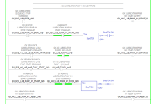
It becomes clearer when you look at the actual outputs (and also the SFC):

1712415760496.png
 
It becomes clearer when you look at the actual outputs (and also the SFC):

View attachment 69279

This is what I am talking about, there is unnecessary logic there that reduces clarity: if GX_SEQ_AC_LUB_LAG_START_CMD value is 1, then both lead and lag pumps should probably have their GX_MCC_LUB_PUMP_M?_START_O bit latched*, so that XIC GX_LUB_PUMP1_LAG in the middle branch of the middle rung is not needed. Again, IMNSHO.

* protecting *_START_O from affecting a faulted pump is done somewhere else

Million-dollar bearing; I don't envy you on this one.

And I am just thinking out loud; you should not do anything based on my say so; get as many invested people as possible to review the final arrangement.
 
Yeah, I get your point.

If I would be doing hardwired relay logic or if I'd use a really limited old PLC I'd go this way and dust the old Karnaugh maps. We don't really need to do it anymore wityh modern PLC's, and I don't mind a couple more tags that I can always use on a "True".

The last screenshot I showed is on an output logic DWG that we use to do commissioning as part of engineering documents, so I can just send the noob to do it and it's clear enough that he cannot miss the point.

Then the customer have it's own crew once we're gone that will use these prints to troubleshot and they aren't seasoned programmers, they are often electro-mechanics or electricians so it needs to be the easiest it can be so I don't have to take a flight to BC to fix something they'd have get if I didn't use an XIO and blew their mind.

We are trying to keep it as much easy as we can so the customer doesn't need to rely on us for everything. Mostly because once we're done with a rehab we don't have time and we're on the next projects, and hiring is hard these days.
 
Ah, gotcha.

And I apologize, but one more thing: what's with the XIC *_STOP_CMD XIO *_START_CMD on the unlatch rung, and vice versa on the latch rung? It appears you are trying to ignore cases when both stop and start command values are 1, but the coded behavior will follow the "first pressed" and "last released" rules (I am assuming those are driven by buttons); is that what you want?
 
And I apologize, but one more thing: what's with the XIC *_STOP_CMD XIO *_START_CMD on the unlatch rung, and vice versa on the latch rung? It appears you are trying to ignore cases when both stop and start command values are 1, but the coded behavior will follow the "first pressed" and "last released" rules (I am assuming those are driven by buttons); is that what you want?
Yes, these are manual commands from HMI buttons. I pulse the commands for 3 seconds. These tags should say _MAN_ somewhere in there, thanks for the note.

90% of time, I would have 2 different outputs, in this case a hardwired seal-in NO for the start and one NC for the stop. But here I only have one output that I need to latch to keep the pump running.

I do that to prevent the operator to quickly cycle between start and stop, some devices like motors don't like that, and to prevent to break something when both outputs aren't designed to be operated at the same time like with some weird valve operation design.

So basically I just put the interlock everywhere even when not needed.
 
Last edited:
Yes, these are manual commands from HMI buttons. I pulse the commands for 3 seconds. These tags should say _MAN_ somewhere in there, thanks for the note.

90% of time, I would have 2 different outputs, in this case a hardwired seal-in NO for the start and one NC for the stop. But here I only have one output that I need to latch to keep the pump running.

I do that to prevent the operator to quickly cycle between start and stop, some devices like motors don't like that, and to prevent to break something when both outputs aren't designed to be operated at the same time like with some weird valve operation design.

So basically I just put the interlock everywhere even when not needed.
I don't know how you coded it, but I wonder if that interlock actually does what you want it to. If I pressed start at T=0s, and stop at T=1.5s. that logic would latch a 1 from T=0s to T=1.5s, and then unlatch a 0 from T=3s to T=4.5s.

I would do the delays like this, which ensures that the process never sees Stop and Start commands within 3s of each other (or whatever delay is in the TONs), and if the Stop is pressed before the Start has been held for 3s, then nothing is seen by the process. Obviously it might be cleaner to put the delay TONs on separate rungs, but this is just the proof of concept. In the example above, neither the latch nor the unlatch would write anything.

1712415760496.png
 
I see your point.

Physically, like it's done, you cannot send the start and the stop at the same time from the screen(s), and only one screen at the time is allowed to operate.

Then I have a double confirmation for each command on the HMI. Let say you select the pump, the popup open, you select start, then select Execute. The popups stays on for one more second then you can select the pump again, select stop then execute. If you're really quick and accurate that can be done in let say 1.5-2 seconds after the first command.

The behavior you're describing is correct. You send the start, the latch goes in. Then the stop command comes after let say 1.5 seconds like you said, inhibiting the start command but anyway PLC already acknowledged that command. And then 1.5 seconds later (3 seconds from the start command first came in) the start releases, letting the stop kick in.

So, for my part, that means that the stop still cannot be issued before 3 seconds after the start, and vice-versa, and that's good enough for me. It cannot be that the operator just hit the stop by mistake anyway, he needs to confirm each command each time.

Also I hate that I need to create a tag for each timer, even if I use an array of timers.
 
No offense, but if you're arguing for clarity by using multiple tags, then those long delineated tag names aren't the way to do it. Why aren't you using UDTs for a pump type? Instead of

GX_SEQ_AC_LUB_LEAD_PUMP_START_CMD

Something like

GX_ACLube.LeadPump.StartCmd
GX_ACLube.LagPump.StartCmd

Is much easier on the eyes. Long tag names in all CAPS should be avoided. Use the descriptions to tell the story, not the tagname.
 
I understand your points. This is a question of philosophy.

I agree with the "all caps" but we've been doing that since 20 years now, not easy to get the older ones and some customers to change. On that project at least I managed to remove the all CAPS from the screens since it's not our main customer and I can "try" things. I like it better this way.

For the UDTs, first I simply just don't like to use them, always had trouble back tracking those tags when they're hidden in a UDT. Also, most of our projects ends up with enough customization needed that many times 2 of the same devices are different. It's not like it's a line-up of 40 VFD from the same brand with 30 times the same IOs I need to pull from there.

So, I don't have enough devices that are replicated to "justify" to go this way. To pile on that, in that particular project, I need to remap in Modbus, which means that I'd need to address the binaries as integers if using UDTs, and I'd need an integer for the BI and another one for the BO since they are not in the same address pool, meaning probably 2 UDTs for... 2 pumps? With 4 BI and 2 BO I can do it by hand, I don't think it's worth it. I haven't tried but that would probably lead to a mess in SMC and InTouch (since we're only using Modbus, not ABCIP).

For the tag names, I have my habits with Schneider FBD where we don't see the descriptions as easily as on a Rockwell Ladder, so we let the tag tell the story. 99% of the time I don't need to refer to the SCADA List to use the tag I want since we've been using the same structure for a while now, and most of the points are always present. Example I know that I can type GX_SEQ_AC_LUB_LAG_PUMP_START_CMD to call the start for the lag pump. I know that I can type GX_PM_COM_F to interlock a logic when I lose the comm with the power meter. I don't need to look for it.

I remember a project we were going to rehab where it was BI0000...BI1000 as tag names, or something like that, don't remember the exact range. Even with the descriptions there, it's a pain to work with that. It was a Schneider FBD project, so all I was seeing was the tags on blocks, I needed to select each tag and check the proprieties to see what it was. With our own tags, I can look at an 8 inputs OR FDB and just with the tags I can tell you what the block is doing and what are all the inputs since the tags are telling the story. And this is why I do that.

We do 95% Schneider PLC, it's my first units with a Rockwell PLC since we don't recommand it when the customer wants to use Modbus, but the customer really wanted Rockwell PLCs for some reason. So in order to not confuse everyone that work with us, we mostly try to replicate what we're usually doing, but in LD since the FDB editor of Rockwell is slowing down the CPU and is a mess to work with.
 
Last edited:

Similar Topics

Hi, What would stop an OSR from outputting? I had the attached program running for weeks without a problem, now the OSR won't output when the rung...
Replies
4
Views
1,674
So I have micrologix 1100 program that controls sonic welding system. The ladder logic currently sents output to welder to allow cycle to start...
Replies
5
Views
3,421
Is it possible to use the OSR instruction with a micrologix 1200? I am trying and getting "rung 1 ins 7: invalid output instruction position!" It...
Replies
1
Views
2,861
Hi, I am reviewing somebody else's logic and I find the following: |----(some logic)----[OSR StorageBit OutputBit]-----| |----[XIC...
Replies
2
Views
3,647
I was looking through code yesterday and found where someone used a OSR to initiate alarm notification. However... the OSR occurs in a routine...
Replies
4
Views
5,421
Back
Top Bottom