Omron Zen programming help needed for R.R. Museum signal.

Jeff M.

Member
Join Date
Dec 2014
Location
Birmingham, AL
Posts
8
Our local non profit railroad museum has a railroad signal that we need to program to operate in a specific manner.

The lighting in the signal is just standard incandescent back up type automotive bulbs that can run off of either ac or dc voltage at 12 volts.

The signal is a 1930's STOP signal. If you picture a traffic light type set up except with four sections with the S being at the top and the P at the bottom you will have an idea of what we have. I will also attach a vintage 1935 ad for this type of signal)

We have an Omron Zen controller (10C1A-A-V2) as well as the software and computer cable to connect to the Zen controller. While we have all of this, we don't know how to program it. If someone could help us out it would be greatly appreciated.

We need the lights to operate in this fashion using an external trigger (switch). The sequence will start with the S light illuminating and staying lit then the T light illuminating and staying lit, and then the O light illuminating and staying lit and then the P light lighting and staying lit - pause for a couple of seconds and then all lights going off - then all four lights illuminating STOP at the same time - hold for a couple of seconds and then repeating the sequence until told to stop by an external switch.

We plan on simply having the ZEN operate four external relays that will go to each lamp with the low voltage power running to those relays. All the ZEN has to do is operate those external relays. We would also like to have the ability to push a switch and have all lamps stay on continually for a lamp test as we have capability on other signals and sometimes when people photograph our signal display it would be helpful to have all the lights on and that just makes it easier. We can run the two standard crossing signal lights off of another device BUT..... if the ZEN (with expansion module as I think the main controller only has 4 outputs) could alternately flash those two lights at 45 flashes per minute, that would be even better as that will eliminate another device necessary for this signal. We could have two external relays fed by the low voltage power supply for these two lights as well. The ZEN would just have to activate those relays.

We have standard relays and time delay relays controlling other signals but were going to control this one with the ZEN controller since what it needs to do is more complex than what the other signals do.

So we know what we need to do but we don't know how to do it. I am sure it is some sort of simple. Is there anyone that could write up this program so that all we have to do is transfer that program to the Zen controller?

Any help would be greatly appreciated. Sorry for the lengthy description but I wanted to get all the information needed in.

1935 STOP signal advertisement.jpg
 
Lancie1 here on the forum is very good with this type device. Maybe he will see your post and reply. In the meantime, I will start to develop something when I get the time.
I think that adding an expansion module for the crossing lights will work just fine with the necessary programming.

Your description is very good compared to many. I would like to ask a few more questions.
1. Is the external trigger (switch) maintained or momentary? In other words, is the start and stop switch one device like a ordinary house light switch or two push-buttons, one for start and the other for stop.
2. What is the time delay or dwell of each letter before the next letter comes on?
 
Last edited:
Here is my 1st attempt, the timing values may need adjusting, I tried to use two seconds betweeen event changes. I used start and stop push-buttons. I didn't include the crossing lights flashing. I will try to get that done as a revision.

Edit:
I know the stop button is inverted and not failsafe. I needed it as shown to test and the application doesn't really need to be failsafe.
 
Last edited:
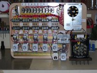
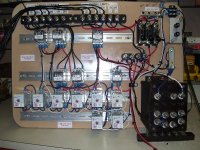
Ok to answer your questions. The other signals all have their own controls that operate them. For example I will attach a photo of a couple of controllers I built using off the shelf relays and standard railroad lamp power supplies and what not. (LOL I can figure that out but I cant figure out how to program the ZEN thing. Go figure)

Anyway each of the controllers starts with a 120 volt input and that input either turns on a power supply and or triggers a start relay on the individual signals. That being said, I can connect it to work using an external relay that will energize with the 120 volt input and have the relay output a contact to start the ZEN sequence, or I am open to suggestions.

Right now the entire signal display starts when a visitor pushes a button that is a dry contact switch that starts a timer which in turn, energizes relays and sends 120 volt power to all the signal control panels. When the timer energizing the starting relay for the whole display times out, it shuts off the power to all of the signals at one time.

If we used a relay and have the normally open side start the ZEN when 120 volts is applied to that relay, and then when power was removed from the control relay, the normally closed contacts would open and make another connection, which could be a stop switch input to the Zen. If need be we could use a double pole relay and separate the start and stop functions (if for some reason they couldnt share a common connection the way I described) Does that make sense?

Your second question referring to the dwell time between each light illuminating is about a second or maybe less. It runs its cycle pretty fast because the aim was to get the motorists attention so it had to not take too long to spell out the word STOP. I had a friend that was a signal maintainer that said they had these until the 1950s when they started taking them out. He said it was because people that couldn't read might sue the railroad because they didn't know what the sign said and the railroad considered them a liability. Go figure. I figure they were probably a lot of maintenance as well.

I input the program you attached into the ZEN software on my computer here at home but I couldn't get it to start and do anything.

The information below isn't relative to this signal but just explains the photos of a couple of standard relay controllers I built for the museum's signal display.

I know it could have been greatly simplified using something such as a ZEN for each but I did what I could with what I knew how to do at the time. Someone suggested using one PLC for all of it but I want it relatively idiot proof and so that if one signal has an issue, our whole display doesn't crash, or the PLC have an issue and none of our display work. Anyway, the file labeled controller is for a signal we are going to install that has nine lights in a circle. The lights have to illuminate in vertical, horizontal, and two different diagonal directions separately depending on the meaning of the signal. I made the controller where it would go through every aspect possible for the signal. The diodes are to prevent back-feeding from lights used in separate indications.

The other photo that says Searchlight is for three signals each having one bulb but a mechanism in each that moves either a green lens or amber lens in front of the lamp to change aspects . They work with polarity switching so that controller I made accomplishes that. With no power to the mechanism a red lens is in front of the lamp as a fail safe indication of stop.
 
Revision #2

Revisions for time, hold to run S T O P lights, added crossing lights, added test lamps for S T O P lights. All inputs require the signal or push-button to be maintained during the entire time a feature is needed.
 
Last edited:
Here is briefly how I tested the program. Unzip the file. Open the file with the Zen software. Mouse over to the ZEN tab, Left click, then, scroll down to the Start Simulator button, Left click. Start Simulator, OK to continue box opens, Left click the OK button. Mouse over to the ZEN tab, Left click , then, scroll down to the Change Mode, Left Click, then Left click on Run. Mouse over to I0 button on Simulator, Hold Left Click to start S T O P sequence. Mouse over and hold I1 for the Test Lamps and I2 for the Crossing Lights.
 
Last edited:
Awesome! I do believe that will work. I just need to tweak the timing between flashes on the STOP and that should work. Having the two crossing lights being controlled by the ZEN will save a lot of space in our control box and eliminate some components. I cant believe you figured this out so quickly especially given my rather lengthy explanations attempting to have someone understand what I was trying to do. You get Four Stars!

After we get this control for this signal up and running I may get another zen and play with it more and see what else we might could do with one. My rather old fashioned way of building our other controllers worked but maybe when they become problematic I can have some ZEN programs that could take their place in the future. Do you have anything that you could recommend that I read that would help someone who knows NOTHING about this, learn how to do it?
 
So glad you were able to get it figured out. Just be careful adjusting the timers and P0 thru P5 values. They all interact with each other. If you need additional help, I will be glad to assist.
 
Guys, thanks for your comments, but there was not much that I could add to JRW's great program. About all I did was add some rung comments and set the timers. I remember stopping at those old crossing lights, so I set the times based on what I remember the lights looked like, but it was decades ago.

I added the Lamp Test switch to the 2 crossing lights so those can be turned on along with the other lamps.

Some of you might be interested in another thread from member "bobc1957" about a similar topic, Hershey Park, in Hershey PA, with a HO-scale model railroad and a complete model amusement park, along with the PLC program.

http://www.plctalk.net/qanda/showthread.php?t=38078&highlight=double+ferris+wheel
 
Last edited:
@Lancie1,
Thanks for the kind words and refining the program. I'm really glad you took the time to comment the program. I was in a hurry to get a working program to Jeff M. and didn't have the time to comment it out. I also forgot the lamps test feature for the crossing lights.
 

Similar Topics

Hi All First time Post I have an Omron Zen that I am trying to program for a chemical delivery system. I have done a few simple programs before...
Replies
12
Views
2,160
I had a new member call me earlier - and since I don't do Omron, I suggested that he post his question here ... he is in the process of joining...
Replies
10
Views
10,132
I am very new so I will try to give as much information as possible. I cannot get a Prolific PL-2303TA USB to RS232 to connect to an Omron ZEN...
Replies
1
Views
1,592
Hi, after 30 years involved with automation I'm actually writing my first PLC program and am struggling a fair bit. My background is mechanical...
Replies
8
Views
1,879
Hi I am setting a system up as per the attached picture, 5 inputs that are always present. These are sensors I have in an injection mould, if...
Replies
5
Views
1,863
Back
Top Bottom