PID Trainer, issue on setup

Yet drbitboy and GIT persist
Why do you care?

Do you not know how to prevent new thread messages from triggering emails to you? (if so, I must then apologize; that would be as annoying as all get out :ROFLMAO:)

GIT has learned that intentionally scheduling a PID is a critical skill. Okay, so it took over a couple of hundred posts to do that, and that is ridiculous, but

  1. that's on us (including you), not him, and
  2. that is funny as all get out, and
  3. if my brother ever finds this thread, he is going to know the answer when he reads the first post, and his opinion of this forum will drop even lower if that is possible,
    1. which is also funny as all get out.
There is to [sic] much trial and error.

My in-PLC simulation, which I have been considering since Post #1, was tuned by theory (that you reminded/re-taught me; thanks!) and correct scaling (though it took a bit; I forgot about KD vs. TD and seconds vs. minutes, LOL). No trial and error. It shows the PLC can do this, if the physical system can be modified to be close enough to the ideal. And you too have been wrong several times, helping to extend the thread.

Maybe if someone had said "attach the code" in Post #2 we would have gotten there sooner.

But why do you care?

it isn't easy and the equipment can't be cheap.

Prediction: wrong on both counts.

(as long as we don't include our billable time, because if we did the entire forum would be the Nth largest economy in the world ;))
 
Last edited:
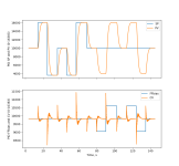
PD control chasing setpoint changes with a perfect bias

Control is a noisy; I believe that is because the simulator integrations are running and that makes the continuous scans run longer, up to a third of the target Loop Update Time (LUT), so even though the average LUT is correct (10ms), its variance is less controlled. If anything, this shows just how robust the P(I)D is.

That would not be a problem with a real process as the scan times would be faster.

Also, I ran some tests and control is okay up to a LUT of 50ms, and does not degrade significantly until a few tenths of a second.

Figure_1.png

Figure_2.png

Just for grins, here is the eight-line Modbus Server that collected the data. It got almost every other sample.
Code:
import serial
import struct
f=serial.serialposix.Serial(port='/dev/ttyUSB0',baudrate='38400',parity='N',timeout=0.05)
while True:
  b = f.read(17)
  if 17==len(b):
    print(list(struct.unpack('>HHHbHHHHH', b)))
    f.write(b)
 
Last edited:
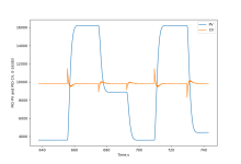
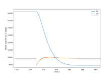
A little more data, the SP and Feed Forward bias, in this plot.

The point is that, with a value of 0 for TI (so no I-action), bias and SP have a functionally similar effect, with opposite sign and different scale of course. The beam always ends up level (modeled as CV = [P + I + D + FFbias] at 9829 = [60% × 16383]).

The bias steps' magnitudes are 780 and 1560, so with a KC of 0.13 that offsets the PV (and Error) by 6000 and 12000 (≡ 780÷KC and 1560÷KC) to counter the bias and bring the beam back to level.

If GIT can modify the physical model to be closer to the ideal model, which is I think mostly about friction (use a slide rule;)), then something like this should be achievable. It does teach a fair bit about how the PID works internally*. Also, even though TI is not strictly needed, it could still be experimented with, which would teach about its inverse-time scaling and relationship with the bias.

* But not so much about tuning, because we don't tune PIDs, we tune systems.

I envision a series of modules:

  • connecting a servo (4-20mA; + and -; scaling)
  • connecting an IR sensor (same; PNP vs. NPN)
  • characterizing the system
    • PID in manual, adjust CV
      • how ball behaves when beam is level, or
      • when beam tilts
      • determining a bias value for when error and error rate are both 0
      • measure the system response
        • this could be some challenging PLC code to a newbie
    • P-only
      • trying to drive error towards 0
      • cycling - why?
      • i.e. how the addition closed loop control changes how the system behaves
      • effect of KC on the system
      • effect of bias on the system: offset
      • effect of SP change on the system: offset
      • effect of scheduling: none; why?
    • PD-only
      • TIME!
        • Why is PID scheduling so important?
        • Why did scheduling not matter for P-only?
      • Plug the system model response measurement results into a worksheet based on the TF
        • solving a quadratic equation should not be too far out of reach,
        • or it could be a canned approach on the sheet.
        • Wow, that's good control, why did that happen?
          • and who do I ask for the worksheet for the next process I have to control?
          • wouldn't it be great if the system designers of the process provided such a worksheet based on a model, so that all I have to do is make some measurements, plug those into the worksheet, and get workable tuning parameters?
      • changing SP does not cause offset this time. why not?
      • changing bias does still cause offset. why?
    • PID
      • cycling again
        • why? windup!
        • back to the PID equation: similarities between bias, SP, and I-accumulation: dX/dt = when E=0 and dE/dt=0.
      • bias no longer causes offset: both are "eaten" by I-action over time.
Because the proper way to do this is to teach Laplace Transforms, but practically that is beyond most who will ever touch a PID, as @Peter has to agree (because he is constantly saying it).

So the next best thing might be to at least give them an idea of what tuning a system with a PID, not just a PID, is about. Also practical things like how to ensure the PID is scheduled and configured properly, where the various knobs are, and where and how they effect (;)) a system response.

Figure_1.png
 
Laplace transforms are a good start. Differential equations are better. In GIT's application we can account for the non-linear sin() function.
In fluid power control the damping is often proportional to the velocity squared. You can't do that in state space and Laplace transforms.


I also don't like Laplace transforms for simulation when the open loop system and controller are looped into ONE transfer function. The problem is that the transfer function doesn't take into account that the controller output is limited to +/- 10 volts or +/-100% etc.


I don't understand what you are doing in the second half the those to graphs unless the second half the the bottom graph is showing the changes in the bias and the second half of the top graph is showing how the ball reacts to the bias changes. The I term will eventually correct for errors in the bias.
 
In GIT's application we can account for the non-linear sin() function.

We don't have to. The elevation of any single point fixed with respect to the beam and level with the pivot centerline when the beam is level is already linear with sin(tilt), exactly and by definition.

The non-linearity in the arm of the servo can be dealt with either by changing the device to a wheel/rack-and-pinion, or by ignoring it because the arm system gain is close to linear near beam-level where fine control is important and anything beyond that is only trying to get back to near beam-level so we don't care.
 
Last edited:
I don't understand what you are doing in the second half the those to graphs unless the second half the the bottom graph is showing the changes in the bias and the second half of the top graph is showing how the ball reacts to the bias changes. The I term will eventually correct for errors in the bias.


That is almost exactly what I said.
 
Just got back in town, I have not had time to go back and read the post YET but I will, then I will try tuning it better. I did want to show how its working now, I am going on vacation next month and I plan on taking the trainer with me and working on it then.

I also had to remove the CV from the trend, just to much noise

Video https://www.youtube.com/watch?v=hXIuVCgjIzE

I also have another motor coming that will be faster so I want to see if it reacts different with a faster speed

New PID.png
 
1) where do you get your table tennis balls?

2) how are you controlling the scheduling of the PID execution (i.e. how often it sees a True input rung)?
 
I have a lot of them, I dont remember where exactly I use them on my other trainers, they are good... not perfect but no where near yours, these look and measure good, they are ITTF approved

As fast as the PLC scans, I am going to try upping the "loop update" later, its at .01
 
As fast as the PLC scans, I am going to try upping the "loop update" later, its at .01


Okay, my bad for not being clear.

1) I am not asking about the value of the "Loop Update" parameter of the PID Setup Screen. I could give a rat's keester about that value.

2) What is the period between two successive instances when the PLC evaluates the rung that the PID is on, when the input rung to the PID is True?

2.1) Are you controlling that period, or is it simply in the continuous task (LAD 2) and executing on every continuous scan cycle. I know there is an XIC B3:0.0/0 on that rung, but I assume that is bit is driven by I:1.0/0 and its value is a constant "1" for long periods of time when you want to run the PID.
 
2.1) Are you controlling that period, or is it simply in the continuous task (LAD 2) and executing on every continuous scan cycle. I know there is an XIC B3:0.0/0 on that rung, but I assume that is bit is driven by I:1.0/0 and its value is a constant "1" for long periods of time when you want to run the PID.

B3:0 is controlled by a toggle switch and is always on, so I am assuming....


GiT said:
As fast as the PLC scans

Every scan, its in LAD2, the B3 was just to reset the system when it started acting up before I found my other issues

Peter said:
I got most of my TT balls from the Paddle Palace and some from zero pong.
Thanks Peter, I will get some on order
 
[As fast as the PLC scans]


Every scan, its in LAD2, the B3 was just to reset the system when it started acting up before I found my other issues

Phew. Over two hundred posts to get to this point. Okay. If you read nothing else, read this post.

The answer you gave above is the primary problem and has likely always been the primary problem since Post #1.

Your current code has done bupkis to schedule the PID. That code is giving whatever the PLC continuous task gives you, probably 1-2ms (i.e. 0.001 to 0.002s, nowhere near the 0.01s you have been telling the PID instruction). So all time-related PID calculations (Integral and Derivative action) have been wrong by a factor of at least five and possibly ten.

You need to, as in must, control the scheduling of the PID instruction. The "Loop Update" parameter in the PID Setup Screen

  1. is you telling the PID instruction the value you use to actually schedule the PID instruction i.e. what you chose for the time period between successive events when the PLC executes logic on the rung with the PID.
  2. and apart from that i.e. being FYI- and read-only by the PID, that parameter has absolutely nothing to do with the actual scheduling of the PID instruction's evaluations.
This device will, I am all but certain, control the ball position well with a loop update time of 20-30ms (Loop Update parameter = 0.02-0.03), perhaps even longer.

You can achieve that schedule reasonably well with a repeating timer making a JSR call (e.g. XIC T4:0/DN JSR 3 in LAD 2) and moving the PID to a rung by itself in the called subroutine. You cannot do it with a XIC T4:0/DN instruction on the input rung feeding the PID in LAD 2, because during the scan cycles when the .DN bit is 0 (the timer is timing but not expired), that will reset the PID internals.

Another option, arguably better, would be to put the PID into an STI routine, but if you are not familiar with the STI file then that may take dozens more posts to get right.

Sidebar

As suggested earlier by @Peter, while you are dealing with that, it would also be worthwhile to time how long it takes the ball to go from the elevated end of the beam to the lowered end of the beam at various PID output CV settings - put the PID into manual and assign values to the CV by hand to get several values. Obviously it will take longer when the beam is closer to level, so a bunch a samples near and either side of level and another bunch far and either side of level would be useful. Once you have that we should be able to give you hard and accurate recommendations for tuning. The best units to use would be the PID output CV units (0-16383), and we would also need to know the beam end-to-end distance in PID input PV units (0-16383). Note that these measurements will change each time you move the device, because the definition of level will be one value on your kitchen counter top and another value on the coffee table watching Netflix. So all the readings should be made with the device in one place and not moved.
 
Last edited:
I have used the PID in LAD2 in the past without issues but I will work on these changes

TL;DR

I love this part. To my mind, this is the only way we teach ourselves how a PLC actually works. The goal is to have the understanding to bring into harmony what we want the PLC to do and what we tell the PLC to do, because the PLC inexorably and mercilessly does the latter while caring not a whit about the former. So we forget at our peril that the onus is always on us :)lolis:) to ensure they are the same.

Add a rung after the PID. Whenever PD9:0/DN is 1, have it subtract execute the following branches (find 3 N7 elements to replace N7:5/:6/:7 if they are used elsewhere):

  • XIC PD9:0/DN
  • BST MOV N7:6 N7:5 ### save last 10kHz RTC value to :5
  • NXBMOV S:4 N7:6 ### store current 10kHz RTC value to :6
  • NXBOTL S:2/14 ### keep low 16 bits if overflow occurs
  • NXBSUB N7:6 N7:5 N7:7 ### subtract current 10kHz RTC value from last RTC value
  • NXBMUL N7:7 1e-4 F8:1 ### convert 10kHz RTC difference to seconds
  • NXBOTU S:5/0 ### Clear any overflow
  • BND
F8:1 will contain a measurement of the actual PID scheduled period. It will be basically equivalent to S:35, but it will be a factor of 5-10 smaller than the PD9:0 Loop Update parameter.

PID is so robust and simple that it still works even when the actual PID scheduling period and the Loop Update parameter are severely mismatched, as long as the process is not too slow or fast, so that tuning values adequate to compensate for that mismatch will fit into the available range for TI and TD.
 

Similar Topics

I have Real PLC but I dont have a real system to have PID Control- any recommendation how can I build such a system- there are some PID trainer...
Replies
6
Views
3,107
I've built a little trainer with a Automation Direct DL05, some pilot lights, switches, a ethernet card and some of the new PX remote I\O. The PX...
Replies
7
Views
4,231
Hi, I would like to assemble a simulator/practice booster pump system that uses PID to maintain steady water pressure under various outlet demands...
Replies
0
Views
86
Hello, I have a motor that we are sending a RPM Speed Output from 0-100% to the VFD. However, the Motor HP needs to be limited to 6000 HP and the...
Replies
3
Views
92
I have S7 1512C controler for controlling 48 PID temperature loop, the output is PWM. Please I need the best, most efficient way to write the...
Replies
13
Views
623
Back
Top Bottom