PID tuning on SLC 5/05

Welp, the overshoot is down to 10-12 PSI. From Post #1, the original problem was that 5PSI of overshoot was okay, but 35PSI was too much. Can you declare success?

It's interesting that setting the CV minimum to 21% delays the response of the valve for 15-20s after the PV crosses setpoint, but I suppose that means the PID uses a CV of 0%, and not the CV minimum, when performing anti-windup reset calculations.

This system is pretty slow and is functionally no different than a level control: IN - OUT = Accumulation; Pressure ∝ Accumulation; the caveat is that we ignore the non-linearities near setpoint. That being the case, I wonder if P-only control, with a Feed Forward Bias of 36% (write a value of 5898 to N16:6), a stiff KC*, and zero for TI. There would be a small PV-SP error offset, but it might be acceptable.

* e.g. 10 or 20 or 50; you'll know when it's too high. Increasing how frequently the PID runs, e.g. 10Hz, might also help here (Loop Update time is meaningless for P-only).
 
Last edited:
I have some questions:
1. What was wrong with the graph in #100 (Why was there no response to CV)?
2. Why is the first third (#105 curves) CO = 20-24 (although it should be 0)?
3. Please remind if the I-term is set to zero in your algorithm
4. At what point does the PID controller start working?

What I mean is that if the I-term does not overflow (the I-term resets to zero, or the PID controller starts to work near the setpoint), then the PI controller should work very well.
On the #105 curve , in my opinion, the I-term is very large. If the PI "formula" is:

CV = Kc* (1 + 1 / Ti * E * Δt)
then Ti should be increased by several, or maybe even 10 times


That being the case, I wonder if P-only control, with a Feed Forward Bias of 36% (write a value of 5898 to N16:6), a stiff KC*, and zero for TI. There would be a small PV-SP error offset, but it might be acceptable.

I suppose it's obvious that different pressure SP will require different biases.
 
I suppose it's obvious that different pressure SP will require different biases.

Yes.

Or they accept the few-PSI offset because a stiff KC may get close enough.

Or the operator tweaks the setpoint once the pressure is steady e.g. PV settles at 123PSI for a nominal SP of 125, so operator bumps SP to 127 to get PV=125. Sidebar: this is the original (pre-PI) form of "reset" to adjust for load changes, and also why the term "reset" became synonymous with integral action. Because functionally, the SP, the bias term, and the Integral (accumulation) term are all doing the same thing, the only difference is how they are scaled into the CV.
 
Welp, the overshoot is down to 10-12 PSI. From Post #1, the original problem was that 5PSI of overshoot was okay, but 35PSI was too much. Can you declare success?
The operators find it acceptable, I will keep trying to get it down to minimal or no overshoot, more for my education than anything else.

It's interesting that setting the CV minimum to 21% delays the response of the valve for 15-20s after the PV crosses setpoint, but I suppose that means the PID uses a CV of 0%, and not the CV minimum, when performing anti-windup reset calculations.

The 21% minimum CV causes the valve to be open enough that pressure takes longer to build. This was done by operator request to provide more time to read tank volumes and calculate oil retention in the charge.

This system is pretty slow and is functionally no different than a level control: IN - OUT = Accumulation; Pressure ∝ Accumulation; the caveat is that we ignore the non-linearities near setpoint. That being the case, I wonder if P-only control, with a Feed Forward Bias of 36% (write a value of 5898 to N16:6), a stiff KC*, and zero for TI. There would be a small PV-SP error offset, but it might be acceptable.

Part of the issue is that the system isn't exactly closed loop, since some oil gets absorbed into the wood, and is thus replaced from the tank, which introduces a random factor depending on the height of oil in the tank.

* e.g. 10 or 20 or 50; you'll know when it's too high. Increasing how frequently the PID runs, e.g. 10Hz, might also help here (Loop Update time is meaningless for P-only).
 
I have some questions:
1. What was wrong with the graph in #100 (Why was there no response to CV)?
2. Why is the first third (#105 curves) CO = 20-24 (although it should be 0)?
3. Please remind if the I-term is set to zero in your algorithm
4. At what point does the PID controller start working?

What I mean is that if the I-term does not overflow (the I-term resets to zero, or the PID controller starts to work near the setpoint), then the PI controller should work very well.
On the #105 curve , in my opinion, the I-term is very large. If the PI "formula" is:

CV = Kc* (1 + 1 / Ti * E * Δt)
then Ti should be increased by several, or maybe even 10 times


I suppose it's obvious that different pressure SP will require different biases.

1. The air to the valve was turned off, so the valve couldn't actuate, thus no response to the process.

2. The graph in post #105 is garbage, the air was still off, no valve response.

3. I term is 0.5

4. There is no increase in the CV until the setpoint is reached; I think with rockwells formula, I would need a derivative term in order to affect the CV before the setpoint is reached. Until setpoint is exceeded, there is no positive error for the P and I terms to calculate.
 
4. There is no increase in the CV until the setpoint is reached; I think with rockwells formula, I would need a derivative term in order to affect the CV before the setpoint is reached. Until setpoint is exceeded, there is no positive error for the P and I terms to calculate.

It is not Rockwell's formula, it is

  1. the generic PID formula,
  2. with anti-windup reset to limit the accumulating I term to prevent the CV from exceeding its hard limits
    1. plus the fact that the primary problem is during startup i.e. climbing from (near-)zero pressure to operating pressure.
    2. Those hard limits happen to be 0-16383 for Rockwell PIDs
1) The generic PID formula sums four terms that each scale values of error (E = PV-SP or SP-PV) in different was over time in discrete steps called loop update times (Δt) to calculate the output CV:
1.1) P - Proportional: KC E
1.2) I - Integral: KC ΣE Δt / TI
1.3) D - Derivative: KC dE/dt TD / Δt
1.4) Bias - a constant to offset
There are slight difference in various PID implementation details:

  • scalings;
  • time units*;
  • whether KC is part of the I and D terms, or the gains are independent;
  • whether the P and D terms operate on Error or PV;
  • how anti-windup reset is implemented;
  • etc.
* e.g. Δt and TI and TD have the same units above; in Rockwell PID, there is a factor of 60 for TI and TD, which have units of minutes, while Δt has units of seconds.

But all versions of discrete valid PID implementations boil down to those same mathematical terms, and will yield essentially the same results when given the same inputs (PV and SP) and equivalent tuning parameters.

A few things to note about some of those terms:

  • If SP is constant, which is usually the case, then its contribution to the P term is constant, and the P term can be replaced with
    • KC PV - KC SP
      • or the negative of that
    • The important part being that the part in blue is constant over time i.e. over multiple loop updates.
  • Again if SP is constant, then SP's contribution to the D term is 0, because dE/dt is equal to dPV/dt
  • The bias term is constant.
What this means is that, for any period where SP does not change, SP and bias perform essentially the same function; stated another way, the effect changing either SP or bias alone could be accomplished by changing the other by some amount determined by the tuning parameters.

2) With anti-windup reset,
2.1) at each re-calculation of
2.1.1) the P, I (accumulation), D, bias terms,
2.1.2) and their sum into a new CV,
2.1.3) based on the inputs at each loop update,
2.2) the PID implementation checks to see if that calculated CV sum exceeds either CV hard limit (0 or 16383 for Rockwell PID)
2.2.1) If either limit is exceeded, the implementation adjusts the value of the I (accumulation) term so the CV sum is within that limit.
Again, how this is actually implemented will vary from manufacturer to manufacturer or even instruction to instruction (e.g. PID vs. PIDE), but mathematically the result is the same: the I accumulation is prevented from driving the CV outside its hard limits.
3) What does this mean for the current thread?
3.1) As has been stated, the reason for overshoot is that the valve remains closed, i.e. the PID CV output is 0, during startup pressurization until the PV pass the SP.
3.1.1) The P and I terms are driving the CV negative; the P term less so each update; the accumulating I term, absent anti-windup, more so each update
3.1.2) The D term is driving the CV sum positive.
3.2) However, because CV is 0 for all of that time, we can be fairly certain that anti-windup is active, so the PID equation
CV = P + I + D + bias
becomes
0 = P + I + D + bias
and by rearranging we can know the integral accumulation recalculated by anti-windup
I (accumulation) = -(P + D + bias)
at least until CV is no longer 0. As long as anti-windup is recalculating that I accumulation, that recalculated accumulation must be non-negative (if the recalculated value were negative, then P+D+bias would be positive and CV would be within the limit i.e. zero or greater).

Note also that those P, D, and bias terms are recalculated from scratch on each loop update. So is the I accumulation, of course, but that calculation is overwritten by the anti-windup.

3.3) As the PV approaches the SP and the CV is still closed, from update to update
3.3.1) the D term (linear with dE/dt) will be decreasing on each update as the pressure rate of rise slows; this drives CV negative, will actually delay the end of anti-windup action, but only slightly, so we will ignore in order to bias this analysis.
3.3.2) the bias term is constant, so it has been long since "assimilated" into the I accumulation (resistance is futile), so it has no effect on CV,
3.3.3) The per-update I (ΔI accumulation) from the PID equation (i.e. KC E Δt / TI) is negative, so it is still driving CV negative, but in smaller steps at each update,
3.3.4) The P term is still negative, but of smaller magnitude on each update update, so its change (ΔP) is actually driving CV positive.

3.3.5) So the end result is that, from update to update, as long as anti-windup is recalculating I accumulation each time, the equation above yields
ΔI accumulation = -ΔP
Where ΔP is positive and fairly constant, and I accumulation, calculated by anti-windup is decreasing (because ΔI accumulation is negative).

3.3.5) Net result:
3.3.5.1) CV will cross 0 when the PID equation calculates a CV sum that is non-negative i.e. that anti-windup does not have to override by adjusting I accumulation.

3.3.5.2) That will happen when the per-update I term from the PID equation is no more negative than what anti-windup would calculate i.e. no more negative than -ΔP, or
ΔI accumulation = -ΔP

KC E
Δt / TI = - KCΔE ### N.B. E is negative and increasing, so ΔE is positive

E = -
E / Δt) TI
3.3.5.2) (ΔE / Δt) is the time rate of change of Error, so also of PV, which rate is relatively constant near the PV=SP crossing for a slow process like this; multiplying that rate by TI will yield the error when CV will be non-negative and anti-windup action will end.
So the final result is that when the valve will open is dependent on the rate of change of PV near SP with the valve closed and the integral time constant TI.

The main result for me is that derivative action will not reduce overshoot when anti-windup is active, which makes sense, because the PID algorithm assumes a change in the CV sum as calculated by the PID equation, will effect a change in PV, and that assumption is invalidated when anti-windup is overriding the PID-calculated CV.

Caveat: I am not sure this analysis is correct; there are a lot of approximations and assumptions (linear behavior near SP, etc.). It seems reasonable, but it predicts CV to become non-negative one TI period before PV reaches SP, i.e. 30s on the trend on Post #100, and that is not what I see.
 
Last edited:
I found an thread from a decade and a month ago that might be useful here: http://www.plctalk.net/qanda/showthread.php?p=530259#post530259

Assuming there is bumpless transfer (as stated by the Manual Mode section of the SLC reference manual page here), a brief few rungs during one scan cycle in manual mode, during which

  • the CV is manually adjusted from a value of 0 to a new value somewhat closer to the eventual value where PV will be controlled at setpoint,
  • and more importantly the bumpless transfer feature instantaneously re-calculates the integral accumulation
    • during the single execution in manual mode
    • as if the controller got to that new CV on its own,
might eliminate a large portion of the overshoot and time that would be otherwise required to generate that integral accumulation.

See the subroutine in LAD 4, and the rung that calls it from LAD 3.. It could be a one-shot triggered operator control during pressurization, it might also be possible to program it to be automatic. Either way a lot of edge cases would need to be considered to ensure it cannot make things worse e.g.


  • that LAD 4 subroutine can be called only once per cycle,
  • is must only be called when the initial pressurization is in progress (e.g. PV has not been greater than SP)
  • it can only fire when the PV is below SP and CV is closed;
  • it cannot fire if depressurization is active.
A PDF of the .RSS from the .ZIP in that referenced thread is attached.
 
I would need a derivative term

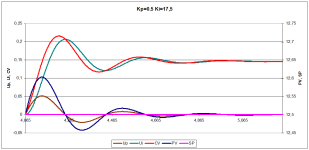
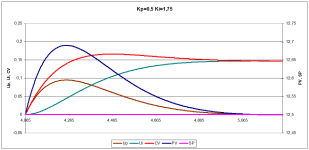
Below are 2 graphs:
1. kp=0.5 ki=17.5 - the system fluctuates because I-term (Ui) accumulates error too quickly, this is what happens on your graph
2. kp=0.5 ki=1.75 - I-term (Ui) smoothly accumulates the error, the system smoothly compensates for the "disturbance".

I.e. you should increase Ti (decrease I-term) - this will reduce fluctuations. And slightly(?) increase Kc - this will reduce the deviation of the PV from the joint venture

I-term overflow.
Depending on your skills, I see three possible solutions to the issue:
1. "Turn on" the PI controller (or reset the I-term) at the moment when the PV exceeds the SP.
2. Enable PI controller when PV > SP * k (less than 1). In this case, some opposite value of the I-term will accumulate, but I think that by choosing a proper k, the system will be quite functional. The implementation of this approach is simpler than point 1
3. As drbitboy suggested, use P-only + bias.
If the PIDE does not "know how" to calculate negative CV, then the bias must be defined at the smallest value of the SP.
Obviously, the value of kp=ks must be quite large

kp0_5 ki17_5.png kp0_5 ki1_75.png
 

Similar Topics

Hello, I'm having a lot of trouble tuning a PID loop on a SLC 5/05. Can someone tell me if I'm doing something wrong? Please see attachment to...
Replies
8
Views
3,829
Hi, I have a system (see attached illustration) that is PID controlled. The pump is used for the injection of chemical from the tank to the...
Replies
5
Views
4,584
Hello, I am using a AB SLC5/05 PLC & using the PID insrtuction for a single loop control. I have assigned N10:0 as the control block starting...
Replies
4
Views
4,973
Hello, I am attempting to tune a PID loop on a process. The process involves a valve with electronic actuator that has quite a high deadband...
Replies
10
Views
2,198
so i have 4 25gpm wells feeding a 1000gal tank (T-1), with an additional 15gpm from a decant tank for 3hrs every 12hrs. P1 and P2 both controlled...
Replies
154
Views
35,936
Back
Top Bottom