PID tuning woes

For all of you popcorn eaters out there ...
64ef95eebc406d900ef473af8b9f561a.gif

...

What is a ballpark time constant, in milliseconds, for a VFD to run a pump like this? E.g. if the current speed reference is 40Hz and the pump motor is running at that 40Hz, and the PID bumps that by 1Hz to 41Hz, how long does it take for the pump motor to get to 40.63Hz? And is an exponential model even a reasonable approximation?

Or is this process so slow that motor response is irrelevant, which seems more likely?
 
Last edited:
@mobil1syn:

1) PID configuration, graphical

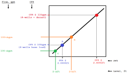
Let's say the PID is configured like this image:
Untitled.png
  • The horizontal axis represents the level input, converted to PV%;
  • The vertical axis represents the CV% output, with tiepoints to actual gpm flows at certain CV% values
  • The plotted black diagonal line expresses the relationship between the input PV% and the output CV%.
    • So if the in the input PV% (representing level) is known as a single value,
      • then the output CV% (representing flow) is also known and can be only a single value.
    • E.g.
      • at a level of 2ft, the input PV% is PV%(2ft) and the output CV% is CV%(100gpm), and the Pump 1 flow is 100gpm.
      • at a level slightly above 2ft, e.g. 2.1ft, the output flow would be slightly above 100gpm.
      • at a level slightly below 2ft, e.g. 1.9ft, the output flow would be slightly below 100gpm.
2) For the following few items, assume base load i.e. inflow is 100gpm.


3) On any given PLC scan cycle, there are only three possibilities for the Tank 1 level:

  • The Tank 1 level is below 2ft; or
  • the Tank 1 level is exactly 2ft; or
  • the Tank 1 level is above 2ft.


4) Case A, level = 2ft, Pump 1 flow = 100gpm

  • On any given PLC scan cycle,
    • the PLC senses the level at 2ft, and the PID, using the plot above, sets its output to CV%(100gpm) i.e. to whatever value makes Pump 2 pump water at a rate of 100gpm
    • Water is coming from the wells into Tank 1 at 100gpm, and
    • Water is being drained from from Tank 1 by Pump 1 at 100gpm.
    • The net flow into the tank is 0gpm (= 100gpm in - 100gpm out)
  • From then to the next PLC scan cycle,
    • since the net flow is 0gpm,
      • the level does not change.
  • On the next PLC scan cycle,
    • the PLC senses the level at 2ft gain, and
    • The PID does exactly the same thing as the last scan cycle
  • So neither the level nor the Pump 1 speed reference changes for as long as the inflow remains at 100gpm.
  • God is in His heaven and all is right with the world


5) Case B, level = (2+Δ)ft, Pump 1 flow > 100gpm

  • On any given PLC scan cycle,
    • the PLC senses the level above 2ft, and the PID, using the plot above, sets its output to a value that makes Pump 2 pump water at a rate slightly greater than 100gpm
    • Water is coming from the wells into Tank 1 at 100gpm, and
    • Water is being drained from from Tank 1 by Pump 1 at a rate greater than 100gpm, let's call it 101gpm.
    • The net flow into the tank is a negative value, -1gpm (= 100gpm in - 101gpm out)
  • From then to the next PLC scan cycle,
    • since the net flow in is negative,
      • the level drops slightly
      • I.e. since the level was initially above 2ft,
        • the dropping level means the level moves toward the 2ft level
  • On the next scan cycle, the level may be any of the possible cases: below 2ft; exactly 2ft; above 2ft.


6) Case B, level = (2-Δ)ft, Pump 1 flow < 100gpm

  • On any given PLC scan cycle,
    • the PLC senses the level below 2ft, and the PID, using the plot above, sets its output to a value that makes Pump 2 pump water at a rate slightly less than 100gpm
    • Water is coming from the wells into Tank 1 at 100gpm, and
    • Water is being drained from from Tank 1 by Pump 1 at a rate greater than 100gpm, let's call it 99gpm.
    • The net flow into the tank is a positive value, +1gpm (= 100gpm in - 99gpm out)
  • From then to the next PLC scan cycle,
    • since the net flow in is positive,
      • the level rises slightly
      • I.e. since the level was initially below 2ft,
        • the rising level means the level moves toward the 2ft level
  • On the next scan cycle, the level may be any of the possible cases: below 2ft; exactly 2ft; above 2ft.


7) It is hopefully obvious that,

  • if the measurement is farther above or below the 2ft level and the inflow remains at 100gpm,
  • then the magnitude of the net flow will be greater,
    • which in turn will increase the rate of level change,
    • but the key thing to understand is that. in all possible cases, the level will always move toward 2ft, at least initially.


8) It should also be obvious that this is the P-only case,

  • Where Kp is the slope of the line, and
  • it will be stable,
    • That is, the level will not cross the 2ft point,
    • with the caveat that the there is an upper limit Kp value that is dependent on the actual loop update time.
    • E.g. to create an illustrative, but extreme and unrealistic, example:
      • if the net flow was of magnitude 10gpm, and
      • the actual the loop update time was a few hours,
      • then on that next scan cycle the level could easily cross the 2ft point.
 
You forgot about the ramp up/down times setting of the VFD


I didn't forget them, I ignored them ;).

But yes in any high-fidelity model, they would need to be taken into consideration.

In this case, with such large tanks, I suspect the only place where they would contribute is in response to the noise in the level measurement.

If given free reign, there would be a filter on the level measurement (moving average or exponential should be good enough; Kalman and its relatives would be overkill, but they would work just as well).
 
P.S. that graphical approach implicitly ignores non-linearities in the CV%(gpm) relationship, but as long as that relationship is monotonic it is unlikely to change any of those conclusions.
 
NR2F9HW.jpg


OK i *think* i grasp why Peter is so annoyed with me thanks to the discussion between drbitboy and Max let see if i understand things correctly. the picture was a huge help, it allowed me to translate it to a 4-20ma signal problem in my simple brain.

P-1
flow
50% - 50gpm
70.6% - 100gpm
88% - 135gpm

level
1.5 is the acceptable low level
2.3 is the desired set point (which is completely meaningless since flow is king, but a value non the less)
4.0 is the upper limit

38% range on the CV : 2.5ft range on the level : Kp=i need to redo my math


P-2 flow
50% - 71gpm
67.5% - 100gpm
90% - 138gpm

level
1.5 is the acceptable low level
3.5 is the desired set point (which is completely meaningless since flow is king, but a value non the less)
4.5 is the upper limit

40% range on the CV : 3.5ft range on the level : Kp = i need to redo my math
 
Last edited:
Well done, I sincerely appreciate your humility and tenaciousness; you will succeed. It is by no means easy to enter the hallowed gates of PID heaven*, so Welcome! We're having jackets made up.

* a.k.a. gobbledygook to the non-cognoscenti, but it makes sense and works for the rest of us.

P-1
flow
50% - 50gpm
70.6% - 100gpm <= We don't care, by a similar rationale to "desired set point" below; but CV% and gpm will end up here anyway between decants, do you agree?
88% - 135gpm <= was 85% - 125gpm in Post #1, but we don't care, because it's just numbers

level
1.5 is the acceptable low level
2.3 is the desired set point (which is completely meaningless ...) <= agreed; seeing this comment make me all but weep with joy.
4.0 is the upper limit

38% range on the CV : 2.5ft range on the level : Kp=i need to redo my math

You did the work, I'll save you the time**: see below and the updated google workbook here, sheet t1_p1_auto_p-only; note how the units cancel!

** but please do take the time to ensure you grok why each is value is where it is, numerator; denominator; numerator or denominator of denominator. Please feel free to ping here or via DM if you don't understand something.

Code:
CV% operating range         38%
-------------------  =  -------------  =  622
                        2.5ft
PV% operating range     ------ * 100%
                        4095ft
 
Last edited:
What is a ballpark time constant, in milliseconds, for a VFD to run a pump like this? E.g. if the current speed reference is 40Hz and the pump motor is running at that 40Hz, and the PID bumps that by 1Hz to 41Hz, how long does it take for the pump motor to get to 40.63Hz? And is an exponential model even a reasonable approximation?

Or is this process so slow that motor response is irrelevant, which seems more likely?

We are not even at the beginning of the P(I) tuning yet. The graphs show noise in the level signal, so I suppose that the P(I) setting will not be very aggressive, and if a limited change in flux is really required, then the control will be very slow (I dare to assume 0.05-0.005 Hz / s)
 
I think you can ignore the VFD ramp up and ramp down times because they are short compared to how fast the levels change. VFDs can ramp up and down very quickly. I/we have controlled lots of VFDs. Some on rotary shears where precise motion is necessary.

Don't use an integrator! How many times do I have to say that an integrator is not required on a level control system unless the level must be controlled precisely. This application doesn't require precise control. A bias can be used to help getting the proportional band set right or even move it up and down to respond to the process up or down stream. Proportional bands are in the KISS category in the scale of complications in the range of KISS to Peter geeking out with some algorithm no one has heard of before.

.
 
Cannot wait to see the next trend.

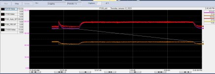
so some frustration today but overall it was a success. the process works, not stoked to have the PIDs scaled differently but it was proof it works. the scaling is just numbers at this point.

p-1 got scaling based on the pressure transducer, which had to be swapped out because the other one got water logged. so instead of 0-5psi it is now 0-15psi, less than ideal but you take what you can find in a pinch.

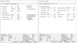
p-2 was structured around the 4095 scale. there is something with the p-2 PID structure that updating the scaling just creates havoc and sends the CV straight to zero. so i did the math around 4095 and let it ride. the unfortunate things is the HMI input was limited to 100 for the Kp, so without the access to the code i would have never got there and have to be online if i want to make changes. going to have to address that for the future.

not sure if i want to keep the 4095 scaling moving forward to avoid the range issue you brought up when discussing it with Maxk or possible discuss making the scale values (HMI inputs) tie into the values for the PID logic.

Again i appreciate all the help and am sorry for being THAT GUY, since i couldnt step back, detach and take a look at things from a different perspective.

230112_p100_pid.jpg 230112_p300_pid.jpg 230112_flowsa.jpg 230112_p100_pid_settings.jpg 230112_p300_pid_settings.jpg
 
there is something with the p-2 PID structure that updating the scaling just creates havoc and sends the CV straight to zero.

Don’t get it. If Unscaled Max=41 Engineering Unit Max=41 Kp=3.59 it should be the same as Unscaled Max=4095 Engineering Unit Max=4095 Kp=358.55. Or I miss something? One thing: you should apply Kp=3.59 first then Unscaled Max=41 Engineering Unit Max=41.

If I understand correctly, the only requirement for the system is not to change tank 2 outflow too quickly and this requirement is now met, i.e. the system implements the required functions. If so, then it really does not make sense to use the integral term (at least this will lead to the need for “time scaling” – I'm scared about it :) ).
Now when system is stable you can “experiment” with Kp to make system “better” (possibly I’ll reduce tank 1 Kp 2-3 times )
If you need to reduce the absolute flow difference of tank 2, or something, please let us know.

But thing I really worried about is a noise. Level signal (PV) is noised, that’s why output signal (CV) noised to (especially fq-100 because tank 1 Kp greater).
Where do signals fq-100, fq-500 come from?
Are the functions of filtering signals, insensitivity of actuators available?
 

Similar Topics

Hello, I am attempting to tune a PID loop on a process. The process involves a valve with electronic actuator that has quite a high deadband...
Replies
10
Views
2,193
Hi everyone, yet another PID problem. I'm hoping I understand enough of the process I'm controlling that my request for help is reasonable. If a...
Replies
113
Views
28,153
A few months ago, I started to look into PID controllers and the tuning of first order processes. This has, partly thanks to you, resulted in a...
Replies
162
Views
62,468
I haven't had to tune a PID loop in a very long time. It's actually a PI loop for a pulse width modulation s.v. What was the name of that tuning...
Replies
16
Views
4,117
Hello, there is anyone who have already used hpmont plc? now i am programming for that plc and have " pid autotuning is not working" issue. I have...
Replies
0
Views
980
Back
Top Bottom