PLC and Terminal block and Sensor wiring selection

I mentioned getting a mulitplever instead of a relay bank simply because it would be cheaper. Instead of selecting the relays one by one, you would instead select the relays with binary coded bits. So it is probably an even better educational experience.

I tried opening the link, but didn't work. I then followed the sections in the link text and navigated to this section: Home > Category: ICs > Category: ICs & Semiconductors > ICs & Semiconductors / Analog/Linear > ICs & Semiconductors / Analog/Linear / Multiplexer or Switch

Hmm. All I see there are what look like microprocessors. I suppose these are the brains of the multiplexer that I'd need to wire up to the inputs and outputs, along with other circuitry... I need to research this first before making my decision. First question that comes to mind is how to send these binary coded bits to it from the PLC... I'm just getting stared in PLCs, but it seems like I'd need a special "binary" card, if there's such a thing; use multiple output discrete channels to send set the bits, or...??? Do you know a link where I could read up on this?

Thanks!
 
Last edited:
I suppose these are the brains of the multiplexer that I'd need to wire up to the inputs and outputs, along with other circuitry... I need to research this first before making my decision. First question that comes to mind is how to send these binary coded bits to it from the PLC...
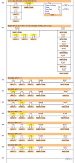
Here is an example of how to multiplex 3 PLC inputs to produce 7 bits or values. Notice that Time is the new variable that is used to control when the multiplexed PLC Inputs are read. For each of the 7 possible On/Off combinations of the 3 inputs, only one of the internal bits will be turned ON. I once used this method to switch 1 analog PLC input to read 9 different analog signals, one at a time.

An Output Multiplexer circuit could use external relays that work the same way to turn 3 PLC outputs into 7 control relays. Typically for PLC multiplexed outputs, one or more seperate control output bits are used to switch the other PLC outputs, so they are used for Function 1, Function 2, Function 3, and so on. A timer in the PLC program can be used to signal when the external relays are switched to a different path.

3-to-7 Input Multiplexer.jpg
 
Last edited:
Here is an example of how to multiplex 3 PLC inputs to produce 7 bits or values. Notice that Time is the new variable that is used to control when the multiplexed PLC Inputs are read. For each of the 7 possible On/Off combinations of the 3 inputs, only one of the internal bits will be turned ON. I once used this method to switch 1 analog PLC input to read 9 different analog signals, one at a time.

Wow! Nothing like seeing things in action. Thank you so much for the ladder logic example and the explanation regarding working this out for the outputs as well!

A concern I have is regarding "turning on/off" the sensors. For instance, the humidity and temperature sensors are both 2-wire ones and when connecting the multiplexer, it would mean that current would be disconnected (wiring as shown in post #28) during a time I'm polling other sensors. Should I be concerned about cycling these types of sensors on/off every hour or so?

Btw, is there a way to enlarge or download image?
 
Last edited:
Should I be concerned about cycling these types of sensors on/off every hour or so?
No, switching every 1 hours should not be a problem. Most likely you could cycle them every 30 seconds, until your relay contacts wear out. You will need to use a PLC timer for the sensor to re-energize each time you turn it on again. In other words, you turn on power, then wait 3 to 8 seconds for the sensor signal to stablilize before "reading" the signal into the PLC.

Btw, is there a way to enlarge or download image?
Yes, there are two or 3 ways. (1)You can zoom in the picture, (2) or you can right-click on it and save it to your computer, then enlarge it and print it out. (3) I have printed it to a PDF file and posted it here.
Also, here are PLC logic and relay wiring schematics for an Output Multiplexer.
 
Last edited:
Sergio,

If you use an Output relay multiplexer, you must make sure that your relays do not switch on/off rapidly. My example allows the 4 relays to only be ON for 1 PLC scan. That will not work very well for physical relays, so you may need another timer (or use comparison instructions) to keep the latch relays on for 2 or 3 seconds.
 
Last edited:
Sergio,

If you use an Output relay multiplexer, you must make sure that your relays do not switch on/off rapidly.

Cool thanks, I think I'm set as far as the logic. I suppose I'll need a small breadboard to mount the chip to and hook up the inputs and outputs. Still looking for a fancy way of mounting this on the din rail. If you have any suggestions, please let me know

Thanks!
 
they show some din rail clips near the bottom

First I wasn't sure this were the ones I could use because they only mentioned soldering diodes, capacitors, resistors, etc, but of course, if the holes are spaced like a breadboard, it shouldn't be a problem soldering the chip socket. Thanks!

Make sure you provide earth to one side in shielded cable to avoid electrical noise.

I will, thanks!
 
http://www.winfordeng.com/products/tta35.php

they show some din rail clips near the bottom

Let me ask you something... Don't these 8-channel multiplexer kits or these 16-channel multlex kits look like a better deal?

I know these don't come with the mounting carrier and terminal blocks, but they look like a great deal. Besides, I could solder terminal blocks to them and even those 4 holes seem to match the DIN Rail Mount shown in the winfordeng site, but that would just be too much beauty...

What do you think???
 
Last edited:
Let me ask you something... Don't these 8-channel multiplexer kits or these 16-channel multlex kits look like a better deal?

I know these don't come with the mounting carrier and terminal blocks, but they look like a great deal. Besides, I could solder terminal blocks to them and even those 4 holes seem to match the DIN Rail Mount shown in the winfordeng site, but that would just be too much beauty...

What do you think???

I think they are probably digital multiplexers and not analog multiplexers. But they provide so little documentation it is hard to know exactly what thier specifications are.
 
I almost bought them, but you're right, I have to make sure they are analog, otherwise what's the point, right?

By the way, I wanted to ask about the wiring of these multiplexers. It may be obvious to most of you, but since I'm a beginner, I wanted to make sure I understood it correctly.

MY UNDERSTANDING IS AS FOLLOWS: The purpose of using these multiplexers is to reduce the number of PLC outputs I need to use to turn relay on/off. So I need to step down the voltage from my 24vdc power supply accordingly so that I can connect the multoplexer chip. I would then turn the plc outputs on accordingly to input the desired signal to the multiplexer which in turn, turn low-voltage output signals that will serve as inputs to electromagnetic relays. Is my undestanding correct?

Thanks for all the good advise!
 

Similar Topics

We're using a lot of Allen Bradley IFM modules (Connecting to ControlLogix I/O cards) in our panels, and are considering replacing them with...
Replies
1
Views
3,364
Dear all How to open .b0$,b1$,b2$,da1,ix$,lx$ allen bradley plc2 files. Please help Thanks & Regards Afeef
Replies
12
Views
4,391
Hello guys i wish if you could help me out with your experience. I must install a PLC on the diesel driven machine and PLC must measure the the...
Replies
3
Views
2,809
Hello, I would like to change the way we currently login to our PanelView Plus terminals. Currently we use the standard terminal features, Logon...
Replies
6
Views
3,313
hello friends i want to send some specific ascii character from PLC to my PC hyperterminal can any body help me in achieving this ?? i am very...
Replies
2
Views
1,907
Back
Top Bottom