Please help me about ladder diagram control conveyor

PluemandNicha

Member
Join Date
May 2023
Location
Thailand
Posts
4
"Hello, I am a beginner learning about PLC. Could you please give me some advice? I want to write PLC instructions as follows:

When the sensor detects a task, turn the sensor on and command the conveyor to rotate.
At the same time, the sensor should start a 1-hour timer.
If 1 hour passes without any new tasks coming in, the conveyor should stop rotating. However, if a new task comes in, the timer instruction should be reset, and the conveyor should continue rotating."

pic is here https://twitter.com/ntmeannicetry/status/1659564025917898754?s=46&t=qzI7fFoAR7iJU9DBxOMm3A
 
That will work to drive the conveyor based on triggering the sensor, to a limit of 1 hour (as desired).

You need to add a way for the sensor to reset the timer. In CLX I'd do either:
XIC Sensor1 ONS x RES Timer1

or
XIC Sensor1 RES Timer1


Depending on desired functionality. Likely the one with the ONS is more useful but they do slightly different things.
 
My second home is Thailand, was there in Jan/Feb
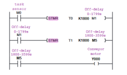
anyhow, you have not said which PLC you are using, I know in Thailand Mitsubishi is widely used, so here is some code in Mitsubishi, however it has been done in FBD (GXWorks2) but easily translated into ladder as it is so similar. Note: I have used two timers as Mitsubishi timers don't go up to 1 hour

บ้านหลังที่สองของฉันคือประเทศไทยอยู่ที่นั่นในเดือนมกราคม / ก.พ.
อย่างไรก็ตามคุณยังไม่ได้บอกว่าคุณใช้ PLC ใดฉันรู้ว่าในประเทศไทยมิตซูบิชิใช้กันอย่างแพร่หลายดังนั้นนี่คือรหัสบางส่วนในมิตซูบิชิ แต่มันได้ทําใน FBD (GXWorks2) แต่แปลเป็นบันไดได้อย่างง่ายดายเพราะมันคล้ายกันมาก
หมายเหตุ: ฉันใช้ตัวจับเวลาสองตัวเนื่องจากตัวจับเวลามิตซูบิชิไม่เกิน 1 ชั่วโมง

Conveyor.png
 
That will work to drive the conveyor based on triggering the sensor, to a limit of 1 hour (as desired).

You need to add a way for the sensor to reset the timer. In CLX I'd do either:
XIC Sensor1 ONS x RES Timer1

or
XIC Sensor1 RES Timer1


Depending on desired functionality. Likely the one with the ONS is more useful but they do slightly different things.
I dont get it sir, would you draw a ladder diagram for me because i am beginner . if you draw a ladder diagram, i think it will be a clearer image.
 
"Hello, I am a beginner learning about PLC. Could you please give me some advice? I want to write PLC instructions as follows:

When the sensor detects a task, turn the sensor on and command the conveyor to rotate.
At the same time, the sensor should start a 1-hour timer.
If 1 hour passes without any new tasks coming in, the conveyor should stop rotating. However, if a new task comes in, the timer instruction should be reset, and the conveyor should continue rotating."

pic is here https://twitter.com/ntmeannicetry/status/1659564025917898754?s=46&t=qzI7fFoAR7iJU9DBxOMm3A

Hi,

Can you clarify what you mean by "the sensor should start" ? Are we considering the sensor an output?

Also what kind of PLC are you using? Do you just need generic ladder logic code? Different PLC's have slightly different ladder logic, for example how the timers work.

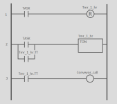
Here is one way to make it work in Allen-Bradley (RSlogix 500 or 5000).

Rung 1 resets the timer to zero (and turns it off) if the task bit goes from low to high.

Rung 2 will start the timer when the task bit is high, and the timer will self-latch until it completes. The .TT bit is on any time the timer is counting.

Rung 3 will energize the conveyor whenever the timer is counting.

You could add a one-shot to Rung 1 if you only want the timer to reset on the initial task coming in, and you could also add the Conveyor_call in parallel to the TON instruction in Rung 2, but I like this way as it keeps it separate and very clean and easy to understand.

Hope that helps.

plc_talk.png
 
I dont get it sir, would you draw a ladder diagram for me because i am beginner . if you draw a ladder diagram, i think it will be a clearer image.


What brand of PLC are you using?

Is it Mitsubishi, as @parky suggested?

Do you have a way to test test code that you write? Perhaps the programming software you use has a PLC emulator or PLC simulator built in?

Also, we want to be cautious about providing direct answers, because if this is an assignment for a course you are taking, and you pass the course because we gave you the answer but you do not understand the answer, and then you get a job programming PLCs because you passed the course, then someday one of us could be visiting your plant and we could get hurt because of something else you programmed without understanding.

If this is a course, perhaps you could post the syllabus, and tell us how much of the syllabus the lectures have covered. It would appear that timers have been covered, since this assignment could be implemented with a timer. Can you describe how you think a timer instruction works, and what are a timer's inputs, outputs, and parameters?

For problems like this specific problem, I find that learning PLC programmers do not understand the utility of the Normally Closed Contact instruction (--|/|-- ; a.k.a. XIO in Allen-Bradley PLCs). I suggest you look at that instruction and think about how it works, and whether it might be useful to you.
 
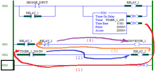
This first image shows an implementation of OP's ladder logic* running on a MicroLogix 1100, and describes the two reasons why it does not behave as desired. Never forget that "The PLC cares not a whit what you want it to do, but it will mercilessly and inexorably do exactly what you tell it to do."

* This version uses a 20s (20000ms) preset, instead of an hour, for convenience, but the operation will be otherwise identical to OP's.
tof_from_ton_00.png


This second image shows the state after the timer expires.

The logic does stop the conveyor once the timer expires, but, as noted above, without a Stop condition to break the Relay 1 seal-in, the task sensor has no effect on any of the logic, so there is no way to start a new task or reset the timer.

@PluemandNicha would do well to review Ladder Logic patterns here, and especially the Start/Stop Circuit pattern here.

The annotation arrows show the convoluted path of the logic, from the Done bit of the timer through Relay 2 and finally to the Conveyor motor output. When ladder logic looks like this, it is in my opinion time to refactor ...
tof_from_ton_01.png


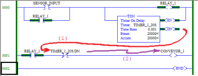
... This third image shows a much simpler and easier-to-read flow by using a Normally Closed contact to directly test the Timer /DN bit (Done bit; .Q in other vendors' PLCs). The logic here is functionally equivalent to the OP's logic in the previous images; the difference is insignificant. Note that, as mentioned by @slick_william, on Allen-Bradley hardware, equivalent logic could instead use a Normally Open contact on the Timer /TT (Timer is Timing) bit.
tof_from_ton_02.png


This fourth image shows the fundamental problem: the Relay 1 seal-in on Rung 0000 prevents the Relay 1 bit from ever returning to a value of 0 once it has a value of 1, and without any logic to drive the input rung branch of the Timer to False, the timer will forever be expired one hour after the first cycle starts, and the conveyor can never be restarted (without a power- or mode-cycle of the PLC, or an external action e.g. by a HMI).
tof_from_ton_03.png


Last edited:
Based on what you posted and this description:
The sensor senses a product on the infeed of the conveyor the latch is set & starts the conveyor, if another pack covers the sensor it resets the timer as the NOT contact in series with the Timer resets it so the conveyor keeps running
If no other pack covers the sensor then after 1 hour the timer times out & resets the latch, there is no need to use the second bit memory this works as on my simulator, only problem depending on the PLC you have most do not have timers that will run for one hour as they are in tens of milliseconds & the max count is 32767 which is less than an hour so you may have to use two timers as my previous post. here is a pure ladder of what works.

Conveyor.png
 
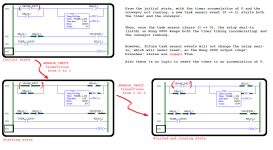
@PluemandNicha: since you are a beginner, there are some aspects of PLCs you might not yet understand.

One of those aspects is that PLC programming is primarily about time, and the scan cycle is the clock.

If you do not know what I mean by scan cycle, then I suggest you watch forum member @Ron Beaufort's video series here. Watch it repeatedly until you understand it so well that you can recite Ron's narration before he says it.

The image below show snapshots of a PLC's state taken at the end of three successive scan cycles. It uses your seal-in rung as an example; the timer has been removed because it is not important here.

The specific idea I want you to understand is that

  • the Normally Open contact with RELAY_1 as its operand, and
  • the Coil with RELAY_1 as its operand,
have effectively different values, even though their operands are the same tag variable.

While those operands, both RELAY_1, point to a value in the same location in PLC memory, the difference between the instructions is when in time they read or write a value from or to that memory.

This is especially clear in Scan cycle 01 in the image:

  • At the beginning of Scan cycle 01, when the PLC evaluates the Normally Open contact with RELAY_1, it reads a value of 0
    • that value of 0 was written at the end of Scan Cycle 00 i.e. the previous scan cycl (i.e. previous in time).
  • At the end of Scan cycle 01, when the PLC evaluates the Coil with RELAY_1, it writes a value of 1, because the rung logic was True at the input rung to the coil at that time.
Understanding this, that
When the PLC reads or writes a value in memory is at least, if not more, important than the value itself
is the key to programming PLCs.

The Start/Stop Circuit pattern (cf. here) is not about logic, it is about time: when the Start condition instruction transitions from False to True, and when the Stop condition instruction transitions from True to False.
seal-in.png
 
If you put Y000 (conveyor) as the output of the second STMR, then you don't need the last rung. However, that STMR instruction would also then write to Y001, Y002 and Y003. As it is, in addition to M1 and M5, the STMRs are writing to M2, M3, M4, M6, M7, and M8.
Untitled.png
 

Similar Topics

please help me . I have to make this ladder diagram and I can’t figure it out :(
Replies
12
Views
340
Q(1) Design a controlling system using DVP-40ES Delta PLC for a threestory Elevator Prototype as shown in the figure below. Show in details the...
Replies
4
Views
2,164
https://onedrive.live.com/redir?resid=31346F822CD6265E!327&authkey=!AGQdmlcOPkXulWM&v=3&ithint=photo%2cjpg All I need to hard wire is one push...
Replies
8
Views
2,306
hello, i am maggiesparky and have visited this forum many times and just love it. well i have a ladder diagram question and ask for your help to...
Replies
13
Views
3,858
Hello all, I have been in the maintenance field for about six years now, and I work around many machines running with the SLC 5/03 and 5/04. We...
Replies
35
Views
9,032
Back
Top Bottom