Hi. I have a microLOGIX 1400, nice kit, cheap and you can get a cheap flavour of RSLogix (vis. micro) just for this controller. Anyway, I have looked and read and can't find any definitive PWM PTO examples. So I ask:
Setting up at function file seems easy enough but to make everything transparent and helpful the function file(s) ie: PWMX:0 or PWMX:1 ... PWMX:2 are the three function files (FF). So we choose 1 of the FF's, say PWMX:2; this FF has 16 parameters; OUT, DS, RS, AS, PP, IS, ED, NS, EH, ES, ER, OF, OFS, DC, DCS, ADD. Most of these are self explanatory and the main parameters to set (I believe) are: OUT (set to the number of the physical output on controller, for ML1400 this is either 2,3 or 4. I have set to 3. OF (the Output Frequency in Hz, I have set to 1000). DC (the Duty Cycle, I have set to 500 for 50%). ADD (Accel. Decell Delay, I have set 100). I am not sure what the PP parameter is, it says Profile Parameter Select and takes a Boolean argument, so either 1 type of wave profile or another but I don't know what the two are.
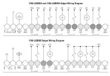
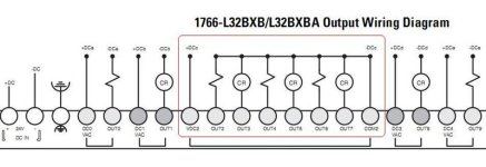
Now, when it comes to the physical wiring I am a little confused. I have a 24VDC motor, PSU and ML1400.
I have the COM(mon); COM2, wired to the V- of PSU.
I have the OUT3 wired to the -of DC motor.
I have the +of DC motor wired to the V+ of PSU.
The motor will not drive, I have changed many of the parameters in FF got buzzing noises but no drive.
Can anyone see what I am missing? Would appreciate a look.
I am thinking now as I write that maybe I need to power the FETs somehow or other????
Any help would be appreciated.
Cheers
Moto


