RSLogix 500 Ladder - Instant Start then Delayed Start for Pump

Join Date
Aug 2023
Location
Mackay
Posts
3
So I very much new to doing ladder coding
I have a pump with a Stop float switch that stops the pump when a sump is low. I want my manual run mode to start the pump immediately when run manual mode is activated and the stop float switch is not active. When the stop float is activated the pump will stop. When the float is not active again the pump will not restart for 5 mins.
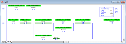
I have a picture of my code but the TON runs first instead of the pump starting immediately. I thought a ONS would work but I guess not.
Code attached.

Ladder Code.PNG
 
Welcome to the forum.

Do you have any programming experience at all? Have you ever heard of AWK/GAWK or Perl?

Do you know what the scan cycle of the PLC is (see here)?

Can you restate the problem as a series of IF-AND-OR-THEN-ELSE statements?
 
Is there an automatic mode, or are you only trying to write logic for the manual mode at this point?


It sounds like there are at least two inputs:

  • low level in sump
    • 1 => level is low
    • 0 => level is not low
  • manual mode
    • 1 => manual mode; run pump is level is not low, possibly with a 5-minute delay
    • 0 => not manual mode
      • possibly equivalent to auto mode?
Are there any other inputs e.g. a high level in sump to trigger the pump to start when in auto mode?
 
There is an Auto mode with a Start Level Switch and High Level Switch. The Auto mode is sorted and working. I just want the pump to not "bounce" on the Stop Level Switch when in manual mode.
 
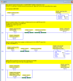
Untested, but it should work. I am assuming Auto mode is active when the Manual mode is inactive (i.e. when MANUAL_MODE_INPUT value is 0).

Once you understand it, you should add comments.
Untitled.png
Note that, if a switch to manual mode (B3:0.0/0 transitions from 0 to 1) occurs while the level is low (STOP_FLOAT_SWITCH value is 1), then the pump will not start until five minutes (300s) after the level rises above the stop float switch.

The reason the ONS did not work is that the ONS output rung is TRUE for at most one scan cycle, and after that the output rung cannot not be TRUE again until the input rung transitions to FALSE and then TRUE again on over least two subsequent scan cycles. Since the ONS would be TRUE for only one scan cycle, maybe less than a millisecond, at a time, the timer will not complete. This could be done with an ONS and a TON, but it will be much uglier than the approach shown.
 
Also, for safety, you might want to have the PUMP_1_FAULT drive a State Coil/Fault Coil pattern (see here), i.e. a fault alarm with a manual reset, and the output of that pattern should replace the XIO PUMP_1_FAULT in the rung that turns on the pump.

That way, when the physical cause of the fault is cleared and the value of PUMP_1_FAULT returns to 0, the pump cannot turn on again until after the fault alarm is manually reset by the operator.
 
Is the 5 minute delay to protect the motor from frequent starts or to make sure the level is high enough for it to run longer before stopping again? Or both?
To protect the motor, I would just put a TOF on "motor running" and make sure it's not timing (".TT" bit is false) before allowing the motor to start. If motor protection is what you're after, I would probably have this happen in all modes.

To make sure the level is high enough, I would put a TON on the low level float to make sure there's liquid there for 5 minutes before allowing a start command. That can be just in the auto mode if you want.
 
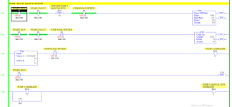
So I thought about it a bit differently and instead of only been allowed to come back on after a certain time I used a CTU and EQU with a XIO on the pump run to reset the counter so that the pump can only come back on if turned to the off position then back to run. This works better for me. Code below.

manual working.PNG
 
Is [PUMP 1 RUN I:0/0] the operator-controlled manual switch that initiates the "manual mode" referred to in Post #1?

Is [PUMP 1 MANUAL RUN COMMAND B3:0/0] the internal representation of when the system is in "manual mode?" And when that bit is 1 you want the pump to run, regardless of the states of the stop float switch I:0/10 or the pump fault input I:0/4.

Also note that the pump fault input I:0/4 will function exactly the same as the operator-controlled manual switch if the operator leaves the manual switch in the on position while there is a pump fault, which could cause manual mode to start without the operator's request.

This is using the CTU accumulated count as an edge-triggered latch; I understand that it seems to work mostly as desired, but that is more complicated than it needs to be, and without rung comments that level of complexity will make it harder to read and understand when diagnosing problems (e.g. if a switch or I/O channel fails).
 
Also, if the [PUMP 1 RUN I:0/0] switch is turned on while the pump is not faulted and the float switch is not active, and the pump then faults and recovers, but before the level drops enough to activate the float switch, then the CTU will count to 2 and the [PUMP 1 COMMAND B3:0/13] will become 0, and the system will drop out of manual mode.
 
If the [PUMP 1 RUN I:0/0] operator manual switch is turned on while the level is above the stop switch, and that switch is left on, then the pump will run and drive the level down and activated the stop switch, which will stop the pump, but if the operator manual switch is still on when the level rises and stop switch deactivates, that will restart the pump, which will drive the level down, etc., i.e. there will be short-period cycling of the pump around the stop switch level.


That was wrong: when the level rises and deactivates the stop switch, the CTU will count to 2, so the pump will not turn on again.
 
Last edited:
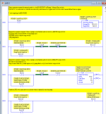
Straightforward implementation with TOF. Note that pump fault state changes while TOF is timing could stop and start pump multiple times, because TOF will always continue timing until expiry.
Untitled.png
 
Last edited:

Similar Topics

How can I achieve the same functionality in Studio 5000? Image 001.png for the old RSLogix500 program Image 002.png for conversion to Studio...
Replies
6
Views
2,519
I had an idea to improve some of my standard programs, and make them easier to modify/expand in the future. Is there a way to address the current...
Replies
9
Views
3,673
Hello all, I have been in the maintenance field for about six years now, and I work around many machines running with the SLC 5/03 and 5/04. We...
Replies
35
Views
9,032
Hello, I am having some problems and I am wondering if I can get some guidance. I will explain the process I am trying to achieve. I am trying to...
Replies
4
Views
4,105
Hi All, I have a couple of questions and would appreciate any help from you guys. I've included my rslogix code and a youtube video of our PLC...
Replies
13
Views
9,424
Back
Top Bottom