RSLogix 5000 Pulse timer (high, low, high) bit

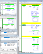
Here is a minimal approach using RSLogix 500 (Micro Starter Lite; see LAD 3 MEASURPULS on the right; the rest is for simulation and testing). RSLogix 5000 would be similar, although the timers could count to 2Ms+ (two billion milliseconds).

This code shows

  • F8:1 - the last total cycle time i.e. the elapsed time between the last two rising edges, s, float;
  • F8:0 - the elapsed time into the current cycle i.e. since the last rising edge of the pulse, s, float;
  • N9:1 - the elapsed time of the pulse signal being high during the current cycle, ms, integer;
  • N9:2 - the elapsed time of the pulse signal being low during the current cycle, ms, integer;
  • the state of the pulse (1=high; 0=low).
Those values could be displayed in an HMI; other values and/or quantities and/or units could also be calculated and displayed e.g. a bar chart of the last 10-20 cycle times.

Caveat
The time values are not exact as they lose a scan cycle here and there, but as that is only a few ms out of several seconds, I suspect that is acceptable.
View attachment 66589

thank you so much, let me see if I can wrap my head around this. It's been a while since I've looked at RSLogix 500 logic.
 
Mark II: added comments. It's simulating a nominally eight-second cycle using bit 2 of RTC:0.SEC*, and showing a twelve-second cycle time for the previous cycle, because (60 MODULO 8) ≠ 0.

* Real-Time Clock SECond-of-minute
Untitled.png
 
So do you really care about the 18 seconds or just that the heartbeat pulse keeps changing? Its dead simple to monitor a heartbeat pulse if all you are looking for is a sign of life. We just need to know how important that 18 seconds really is.

no unfortunately I'm not just looking for a heartbeat. That would have been simple.

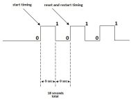
1 cycle = (bit hi+bit low+rising edge of next bit hi) timing the entire time, and start over at rising edge of next bit hi.

I don't know how else to explain this goofy thing.

pulse.jpg
 
thanks buddy! let me see if i can figure this out. too complicated for a simple man.


Watch this video series to learn how the scan cycle works, and how to read ladder logic.

PLC programming is about time, and the scan cycle is the clock.

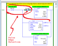
The key questions relating to that image is, when was the value of discrete bit T4:0/EN assigned during the first program scan cycle after the pulse signal (B3:0.0/0) has a rising edge?

Once you know the answer to that question, answer this one: what is the value of bit T4:0/EN when that XIO T4:0/EN instruction is evaluated during the first program scan cycle after the pulse signal (B3:0.0/0) has a rising edge?
 
Hi drbitboy,

Your logic does the trick, a huge part of the trick that is. But it does not zero when it's time to restart clean ready for the next cycle. It always keeps one half of the stored MOV'd value. Here is a link:

drive.google.com/file/d/14QZwDf1Zo6Gu4Tx3fTeVmxzaPFZcToKL/view?usp=sharing

arrgh, probably a typo, just a sec ... yeah sorry, I was sloppy ...

Post #12 is correct; I thought I "fixed" summat in Post #17 LOL. Source B in the ADD should be T4:1.ACC

Nice catch!
 
Last edited:
arrgh, probably a typo, just a sec ... yeah sorry, I was sloppy ...

Post #12 is correct; I thought I "fixed" summat in Post #17 LOL. Source B in the ADD should be T4:1.ACC

Nice catch!

Man! don't be sorry, you have no idea how much you're helping me! ha ha ha h
 
arrgh, probably a typo, just a sec ... yeah sorry, I was sloppy ...

Post #12 is correct; I thought I "fixed" summat in Post #17 LOL. Source B in the ADD should be T4:1.ACC

Nice catch!

drbitboy,

Your logic worked like a charm! My sincere thanks to you. How do you assemble something like this in your head on the fly? How long have you been doing this?
 
TL;DR I "It's just zeros and ones, it cannot be hard" - Jouni Rynö

TL;DR II "Jouni Ryno needs a poke in the eye." @Puddle.

How long have you been doing this?

Programming ladder? About 5y. Although my sensei, such as the forum members here and my brother, have been doing it much longer.

Programming in general? About 45y.

Making mistakes? Much, much longer. This last one improves the skills of the previous two ;).

How do you assemble something like this in your head on the fly?

Sometime I honestly think I don't know.

Every useful computer program, regardless of language environment, is a model of some sub-system of the real world; it helps to have an engineering background* to be able to tie the two together. The primary design choice is the level of fidelity in the model of the real-world subsystem, and that is often constrained by what the chosen language and computing can do (ladder instruction set; scan time and hardware; etc.). All other design choices flow from that. After that, refer to TL;DR I above.

* or to know how to multiply by one, which is essentially the same thing as engineering

You will probably move on because that is what your employer pays you for, and that is fine; I hope you understand what I did, especially the edge detection. But if you don't, you could spend your own time in worse ways than studying and thinking about these few rungs to understand exactly what the PLC is doing and how the different pieces work together: time (scan cycle); bits; compound bits such as integers and timer structures; instructions. It may seem like magic, but it is just zeros and ones, and at some point some folks' brains click, grok, and it becomes second nature.
 

Similar Topics

Hi Guys, I am trying to create a triangle (Sawtooth) pulse in RSlogix 5000 using counters/timers and anything else. I'm not sure what the ladder...
Replies
43
Views
17,027
hello guys is there any 1 millisecond pulse generator in the rslogix5000 inbiult
Replies
9
Views
10,015
Hi all, Anyone knows how to declare a one second pulse in the Rslogix 5000? Is there any command for this function? It does not same like GE or...
Replies
34
Views
86,538
Hi folks, in the alarm manager of Rslogix 5000, the tag-based alarm has been created. But when I tried to change the condition, it was found the...
Replies
2
Views
156
Back
Top Bottom