Shift Register and Debounce questions

Dumbplcguy

Member
Join Date
Nov 2023
Location
Indianapolis
Posts
2
Hi guys,

I am pretty new when it comes to programming. I am working with CX-Programmer and I am having a problem where I have a sensor on my machine and it is supposed to detect green tape on the material and then cut it off. At first the green tape would not make it to the cutter and it would mostly be material instead of the green tape. Then I added a shift register to track the positioning. Now it cuts up until the front edge of the green tape, feeds through a little bit but it cuts into the green tape when it is supposed to cut into the trailing edge of it. I tried to adjust the shift register but it caused the cutter to cut into the material too far ahead of the green tape. Right now in the shift register I have 441-448. How do I get it to cut into the front leading edge of the green tape, have it feed all the way through, and cut into the trailing edge of it?

I also want to note that there is a 100 ms debounce timer that is at #40 when the green tape is detected.

Sorry if this is all over the place as I am new and explaining PLC related problems are also new to me.

Thanks in advance.
 
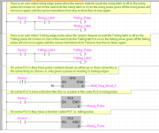
you can use oneshots or what they often call pulse coils.
Some PLC's have in-built functions for example an arrow in the contact or a function called pulse, these can be in two forms i.e. rising pulse or trailing pulse so for the rising pulse this detects the front edge of the part, trailing edge detects the rear edge, the pulse will be on for one scan only.
See attached there should be at least one of these forms of oneshots in your programming software

Oneshots.png
 
Using parky's example number 3: In CX Programmer, right click on the contact and choose Differentiate > Up or Differentiate > Down for the up/down arrows.

Alternatively you can simply use the negated contact (LD NOT) for your shift leg (middle) in the SFT(010) instruction. The instruction operates on differentials by default.
 
There is a distance between the sensor and the cutoff point. How are you tracking that distance?
Your program needs to delay commanding the cutting mechanism once the tape is detected by the sensor. If the speed of the material is constant, then you can calculate the amount of time it take for the tape to travel the distance from the sensor to the cutoff point and use that time as a preset for a timer.
If the speed of the material is not constant you will need some way to measure the distance. That could be an encoder on a wheel driven by the material. Then you need to calculate the number of pulses from the encoder between the sensor and the cutoff point.
A shift register is typically used to keep track when there are multiple pieces between the sensor and the point of action. For example, when there are six inches of material between each tape, and two feet between the sensor and the cutoff knife.
 
I agree with Steve, plus timers are notorious for in-accuracy due to the effects of scan times, it will depend on the speed of the system, however, it would be best if there are timed interrupts available i.e. say 10ms then you could taylor the count in a timed interrupt & get better resolution. also agree with the encoder or perhaps a star wheel with proximity, the more pulses per mm or what ever the better the registration will be. there would probably be a need to use either a high speed input interrupt to count the pulses as it does appear that you have a problem at the moment getting registration correct.
 
Sorry if this is all over the place as I am new and explaining PLC related problems are also new to me.

Little bit, yeah, but it's all part of the process. Here are some suggestions:

Can you post your code (screenshot or PDF, so as many as possible can read it)?

Can you post a sketch of the process, or a photo, perhaps with annotation?

If you search for the terms conveyor, reject, and shift on this forum, you should find many threads about similar processes.

The bit-shifted array (or integer FIFO?) is a model of your process. At its simplest (again, we don't know because of the lack of detail; maybe you already have gotten this far),

  • There is an array of bits where the bit's value at each index in the array models the "green tape" state at some position between the green tape sensor and the cutter that removes the green tape, and possibly beyond
  • There is an edge signal PLC input that models the motion of the material, and/or of any green tape on the material, in the process.
    • This signal could be e.g. a prox sensor detecting sprocket teeth, or each restart of a repeating timer if the conveyor speed is constant.
  • There is a PLC input from the green-tape sensor at some process position upstream of the cutter.
    • For simplicity let's say that
      • this PLC input's value being 1 models green tape being detected by the sensor, and
      • this PLC input's value being 0 models green tap not being detected by the sensor.
  • A few things are controlled by the PLC based on the input, and they happen independently of each other:
    • The value, 0 or 1, of the green-tape sensor's PLC input, is continually written into the array at some index.
      • That index of that array models the position of the green-tape sensor in the process
    • The edge signal triggers a shift all of the bit's values at each index of the array into to next index of the array.
      • Each bit-shift models a fixed linear increment (displacement) in position of all of the material since the previous edge signal.
        • The bit at the last index in the array is shifted off the array and perhaps discarded
        • The bit at the first index in the array is shifted onto the array with a value of 0
          • This models an assumption that the material at the process position modeled by the first bit's index has no green tape
            • That value of 0 may be overwritten by a value of 1 either immediately, or later, when that bit is at the index that models the process position of the green-tape sensor
        • The value of the bit at the array index that models the process position of the green-tape sensor is moved to the next position and so cannot be overwritten again by the green-tape sensor input.
    • There is an index in the array that models the process position of the cutter.
      • The PLC program monitors the value of the bit at that index to choose when to activate the cutter. Perhaps it makes a cut at each transition 1=>0 or 0=>1, or perhaps it initiates cuts
        • just before each 0=>1 transition by looking for a 0=>1 transition a few indices upstream of the cutter index, which models a green tape leading edge just before it reaches the cutter, and
        • just after each 1=>0 transition by looking for a 1=>0 transition a few indices downstream of the cutter index, which models a green tape trailing edge just after it passes the cutter.
The point I am artlessly, but hopefully obviously, laboring to make is that the bits in the shifting array will model the tape/no-tape state of the process at any time, and the indices of the shifting array will model process positions at all times.

The primary design choice of any computer/digital model is the fidelity of the model i.e. how accurately it models the process. Whether the operator's eyes are green is probably not a critical and necessary part of the computer model. Knowing how far the conveyor moves per sprocket tooth is a critical and necessary part of the computer model, because that is part of how you convert between the positions of the green-tape sensor and the cutter and the indices in the bit-shift array that model those positions.
 

Similar Topics

I am attempting to reject a bottle If the label fails. The rejection works fine at normal line speed but at low speed the rejector fires (air...
Replies
35
Views
1,148
Hi all, i have a very slow indexing machine where we are looking to make everything as bulletproof as possible, money is not much of a factor...
Replies
12
Views
3,064
Good morning (EST), I am trying to implement the code below in on an S7-1200. It's barely half a dozen instructions, but I am stuck; I have not...
Replies
26
Views
5,669
Hi everyone I am completely new to using shift registers and am a bit stuck, my shift register works as should, it is for an overhead conveyor...
Replies
55
Views
15,608
Good Morning , I'm developing a Shift Register Program for a conveyor system. I begin the Shift Register on a conveyor that is roughly 128...
Replies
14
Views
3,623
Back
Top Bottom