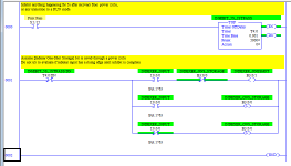
is there any way to make a more robust shift register?

Bobobodopalus

Member
Join Date
Feb 2020
Location
Surrey
Posts
89
Hi all,
i have a very slow indexing machine where we are looking to make everything as bulletproof as possible, money is not much of a factor here. this will be a compactlogix machine so using studio5000


i currently use what i assume is a very normal FIFO shift register arrangement which is triggered by a sensor at the end of the index.


when being asked about potential issues with it the only thing i could think of really is a very unlucky power outage where the motor would come to a stop on the sensor when it is no longer powered, i think they will probably have to live with this but did want to see if any other options exist.


is it possible to tie a bit to a position on an absolute encoder?
i am imagining that i can essentially create my starwheel in the plc putting a can into pocket 1 and then having this can bit tied to that pocket.


sadly i dont know how to achieve this, especially on a compactlogix, would love to know some other methods of shift registers anyone has used.
 
I am having trouble understanding exactly how the power outage affects the PLC model of the process. For example, does the PLC also lose power?

It would help if you could you show

  • a sketch of the process,
  • your current code,
  • a contact trace* of what this "very unlucky power outage" looks like.
* parallel trends of how the bits and the encoder value would be behaving before, during and after the power outage; here is an example from Siemens.

Does this link describe a similar problem?
 
Last edited:
Most PLC programs implement a virtual model of a physical process in the real world. The PLC inputs from the real world process update the virtual model in the PLC. The outputs from the PLC are based on the virtual model and driven by the logic of the PLC program (e.g. sump level high => start pump), and (hpefully) affect the real world process.

It sounds like the problem here is that an event that occurs in the real world process is unknown to - and therefore not modeled by - the virtual model and/or the input system.

Also, OP refers to a "FIFO shift register." That conflates two constructs in Studio 5000: an integer FIFO, represented by an array integers, and controlled by the FFL and FFU instructions; a bit shift register represented by an array of integers or booleans, and controlled by the BSR or BSL instructions; yes a bit shift register has similarities to a FIFO but it is not the same and Studio 5000 makes the distinction in it choice of terms. It sounds like the bit shift register is in play here?
 
yes sorry, a bit shift register.
upon the index home sensor being made the shift register is advanced.


The unlucky power loss would be:
the machine begins an index.
the cabinet loses power just before the index home sensor is made.
the motor winds down and the index comes to a stop on the index home sensor.


so in that scenario the shift register has not been shifted due to the rising edge of the home sensor not being seen which has resulted in the real world model advance in the shift register but not in the plc, would cause half fills or missed crimps etc.


as far as i am aware this has never happened and is a very unlikely situation, but we have a new pharmaceutical customer and they are breaking balls on any minute vulnerability (which is somewhat fair considering the product could potentially cause harm)


sorry im terrible at explaining :s


just as a note this new machine is still in the design phase and can have almost anything done with it to improve it.
 
Last edited:
You can use an ONS and an OTL to determine whether an input came on while the PLC was not in run mode.

imo in general if a machine loses power unexpectedly there should be manual verification that PLC matches real-world status before beginning to run again.
 
You might be able to add bits between the physical stations. When the index begins you shift everything indicating that the indexer is moving and parts are transferring. When you get the index home sensor you shift again indicating that the parts are in the new positions.

The definition of the bits in the shift register will be something like:
-entering sta 1
-at sta 1
-between sta 1-2
-at sta 2
-between sta 2-3
-at sta 3
etc...

When the parts are at the stations, all the "between" bits will be zero. When the parts are between or on route to the next station, all the "at station" bits will be zero.

On power up, you can see if the shift register shows the parts at the stations or between the stations and decide what to do from there.
 
Last edited:
An absolute encoder was mentioned in the OP.

What is that absolute encoder's resolution?

Will it be known what values of that absolute encoder represent index home positions? Maybe the app does not require a FIFO, but a static array with the absolute encoder as a pointer into that array.

Is it possible for the PLC to detect the power loss? Does the PLC lose power in this scenario as well, or should it be able to recover whether it does or not? It is of course be possible for the PLC to detect when it enters RUN mode (first-scan bit).

A power loss is a significant, but hopefully rare, event. If automatic recovery is not possible, the power loss could cause the PLC to stop the machine, and to leave it stopped until an operator confirms its state is correct, presumably after checking for things like half fills or missed crimps. [@plvce already said this]

[edited]
The unlucky power loss would be:

  • the machine begins an index.
  • the cabinet loses power just before the index home sensor is made.
  • the motor winds down and the index comes to a stop on the index home sensor.
so in that scenario the shift register has not been shifted due to the rising edge of the home sensor not being seen, which has resulted in the real world model advance in the shift register but not in the plc
Wouldn't the index home sensor be made when the power comes back up, and then that made sensor generate the rising edge when the power comes back on? Unless the motor winds down and coasts past the range of the "made" sensor positions?
 
Wouldn't the index home sensor be made when the power comes back up, and then that made sensor generate the rising edge when the power comes back on?
I would guess they are using an ONS or some other method to prevent the bit shift from triggering on power-up, so that when power is cycled while it is stationary on the sensor (probably the normal position when cycling power) it doesn't register a shift that didn't actually happen.

EDIT:
drbitboy said:
Unless the motor winds down and coasts past the range of the "made" sensor positions?
If this is possible it is what I would be most concerned about -- you can programmatically check for the sensor becoming made while off, but if the index moves entirely past and is not on the sensor when entering RUN again, there is no way for the PLC to register that it was missed unless another input is being used (such as an encoder).
 
Last edited:
you post is a little vague.
on the indexer, how many positions?
is it servo, stepper or air/hydraulic indexed?
time it takes to index?
is there a sensor at each index position?

let's say we have a 10 position indexer.

when the part is in position.
trigger the index
1. put a 1 in the bit shift register
2. you also have a 2nd shift register using integers.
move position 9 to 10, 8 to 9, 7 to 8, 6 to 7,....and so on.
3. latch a bit and start a timer
when the index is done and you get a confirmation, reset the latch bit which in tur kills the timer. if the timer times out, something went wrong.
NOTE - this will not work if the index has flow controls or the pressure gets adjusted. also, as the indexer wears in, it will speed up.

i did thus on a walking beam indexer and it works great.

plvlce,
if the plc is in program mode, the logic will not latch a bit, the program isn't running. someone please correct me if i am wrong.
james
 
I would guess they are using an ONS or some other method to prevent the bit shift from triggering on power-up, so that when power is cycled while it is stationary on the sensor (probably the normal position when cycling power) it doesn't register a shift that didn't actually happen.

They could put an [XIC first_pass OTU indexer_ONS_storage] rung in to ensure this does not happen, but then if the power goes out when it is already on the index and registered that oneshot (probable default as you note), then it will push an extra 1 onto the FIFO.

Maybe they could implement the edge-detection with manually-programmed one-shot circuits using only OTLs and OTUs, so the state would survive the power cycle.

Then the only problem is coasting complete over an index on a power loss, which perhaps could be handled using the absolute encoder?
 
If it's pharma, just clear the shift register on power up and boot everything off.


This may be the one we should go with to be honest, safest option ultimately.


i am thinking of where all power is lost, PLC, cabinet, machine etc.

the index is only 12 positions, it is a stepper motor with a pneumatic solenoid clutch, the motor speed is adjustable.


Ndzied1's idea is quite nice, i may implement that to my normal index shift registers.


Drbitboy:

Will it be known what values of that absolute encoder represent index home positions? Maybe the app does not require a FIFO, but a static array with the absolute encoder as a pointer into that array.


this sounds like what i was thinking of, using the position of an absolute encoder on the index shaft to keep track of what pockets are full/empty
 

Similar Topics

Good Afternoon , I have the free version of CCW. Version 11. What is the latest version ? Also , is there a version that is purchased that...
Replies
18
Views
6,446
I have a client with a problem. He can't find a temperature controller (40mm x 40mm) that panel mounts, and is of sufficient robustness to...
Replies
4
Views
2,114
Hello, i need to use P_Intlk and feed the Status interlock OK bit to a P_DOut block. However, there's 17 interlocks for this output. How can I...
Replies
1
Views
108
Hi everyone, recently i worked with a cmore panel and have the question that how can clear alarm list whit remote form,right now only can with...
Replies
0
Views
109
Hello, friends, I am trying to upgrade a system that uses an Onrom incremental encoder (E6B2-CWZ6C) connected to a Danfoss VFD (FC360), but now...
Replies
4
Views
274
Back
Top Bottom