Siemens S5 destructive "scratch flags"

QTown

Member
Join Date
Oct 2023
Location
Ontario
Posts
4
New to these forums, I tried searching for this but couldn't find it.


I'm finding this situation frequently in this program I'm converting. As far as I understand, any flag bit above 200 is considered a "scratch flag" which to my understanding is used like a temporary memory bit or local tag.


I'm trying to understand the reasoning behind it's use here. My best guess is the intent was to bypass the timers and Q70.2


If anybody has more info on how these scratch flags were used (in general) that would be helpful. It's use looks redundant to me in most cases. Thanks.


A(
O T 34
O T 35
R Q 70.2


A T 36
A T 37
ON Q 5.4
S Q 70.2


A Q 70.2
)
= F 255.1


AN F 255.1
= F 255.1


A F 255.1
A F 128.0
= Q 66.0
 
I assume this is possibly S5 although same in early S7, that is correct, siemens used fw 200 to 250 as temporary memories (scratch flags) however, if you have no siemens FB's installed then you can use them as normal flags like the rest.
It is common to use those flags even if they are being used elswhere as scratch flags because they are only relevant in the logic shown in your picture.
The logic does not make any real sense
The first bit with the AND Brackets not worked that one out quite yet
F 255.1 will be on if that logic between the brackets is true, if not then F255.1 will be false so it looks like If F 128.0 & F255.1 is true then Q 66.0 will be true but if F255.1 is true on the first bit of logic then Q66.0 will be off.
The other logic ANF255.1 = F255.1 means it will be true if the first logic is false.
See a simulation without the first logic i.e. the timers etc. for F255.1 on or off
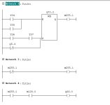
This is not siemens but it is logic so the same, what is a bit confusing is normally Set & Reset coils are not or cannot be used in ladder, however, in siemens STL it will all depend on the RLO of each instruction preceeding it, never seen a set in what would be normally where only contacts could be used so it might be some quirk that the programmer used to effectively invert F255.1 I do not think that the logic as shown would convert to ladder anyway I can simulate that in my IDE & the second pic shows the logic as I see it.
However, it seems to me that the bracket is in the wrong place.
I would have expected

A(
O T 34
O T 35
)
R Q 70.2

A T 36
A T 37
ON Q 5.4
S Q 70.2

A Q 70.2
= F 255.1
Something does not seem right perhaps someone with S5 or S7 could replicate it in STL and check the result of logical operations are.
As I stated it is not normal practice to put coils in line with the AND brackets

logic.png Logic 1.png
 
But It's destructive so wouldn't F255.1 always be on by this logic? If the bracketed logic evaluates to 1 then its F122.1 = true


then
AN F 255.1
= F 255.1


wouldn't do anything.


Then If Q70.2 is False then


AN F 255.1
= F 255.1


would turn F255.1 true as well.


I don't see how it could evaluate to anything but true in the last section.


I'm not that familiar with STL/IL or Siemens S5 so I'm sure I'm missing something.
 
In S5 there are no destructive areas on flags as such it's just Siemens use those flags as temps to store things or trigger them, they often use the same flags/words over & over, imagine you need 28 contacts anded but for display purposes the ide only allows 7 from what can only be described as the power rail & an out instruction on the common rail, however, most IDE's allow more contacts by using a symbol like > arrow to depict it continues on the next line, however, this makes displaying just that little more out of context, years ago some IDE's would only allow so many perhaps 7 or 8, programmers used a trick where they would put say 7 contacts on a ladder line onto a out instruction i.e. F100.0, then use that flag on the next rung plus 6 others, then put the same flag as an output then use that on the next rung, not all IDE's allowed multiple instances of an out instruction on a bit or at least it would warn you, so what happens is the first rung logic is true so M100.0 is true, the next rung 100.0 is still true, but at least one of the other contacts is false so the same flag is not true, in other words rung 1 it's true rung 2 its not true, so the flag is only on for that period, if all the 27 contacts were true then on the last rung the flag 100.0 would be true, If for some reason this same flag was used again for the same purpose it would take on a new role & be forced true or false in that logic.
I have no idea why the original programmer used that logic it is not conventional but works. The actual logic as I see it is that the flag 255.1 in the first bit of logic (if you include the close brackets) if true then on ther next bit the AN F255.1 = F255.1 will turn it off, if on the first rung it is false
then the next rung F255.1 is off so as it's a NOT it turns on F255.1 so in effect the bit is inversed, rather odd way of doing it as why not just use the not contact to energise Q66.0
I think it is a case of there was a problem the programmer was frustrated, changing code at will & eventually got it to work (assuming it does) or the upload of the code has got corrupted at some point but unlikely.
I have seen a similar situation on a mitsubishi, when they started to use the IEC language if the program was written in FBD then it compiled it into the native instruction list like STL, however, if you uploaded it the code would come back as the old ladder, however, because the translation compiler did have bugs some code would come back where a stray contact would be on another rung with no out instruction so would not compile, however, if you used it as statement list is was ok, the logic worked but in effect the brackets (although not used in Mitsi they use other compiler instructions) was missing so could not be translated into ladder.
 
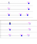
As I realised, to try & explain it can be difficult for others to understand about how a bit can be on & off in different parts of the program so attached is the proof.
I am using a temporary bit to split what would be a very long rung into seperate rungs, yes you could use seperate bits but there is no need & due to how the IDE monitors values i.e. read probably only once per scan or less, however, you can see from the status in on-line monitoring the pattern of true/false bits seems to be wrong as the second rung shows the Temporary bit as false but in that rung it is true, but false on subsequent rungs.

Destructive bits.png
 
I'm finding this situation frequently in this program I'm converting. As far as I understand, any flag bit above 200 is considered a "scratch flag" which to my understanding is used like a temporary memory bit or local tag.


This is usually the case. You need to take extra care if using timed interrupts though - here the flags would be copied to a DB at the start of the timed interrupt and restored at the end.
 
I agree with LD, there is something amiss though, when you convert the ladder version into STL it is not the same.
this would be

A(
O T34
O T35
) ***** missing
R M70.2

A( ***** missing
A T36
A T37
ON M5.4
) ***** in wrong place
S M70.2
A M70.2
= M255.1
I was wondering with those brackets missing/in wrong place, if the RLO will have any effect. The code as posted does work though but not checked the actual operation.
 
I copy/pasted the code from the OP and it converted to ladder as shown. When you save the block however, the editor 'fixes' the code to follow the ladder editor rules and the resultant STL is not identical but functionally the same.
 
Yep I just did it so the bracket positions make no difference to RLO in this case.
I actually re-wrote it in ladder as you would expect & the functionality is the same.
There are 9 combinations of those if rather than use set/reset but probably less if you sorted the logic and use the not contact as shown. what the original programmer has done effectively reduced the code if you try to do it using just contacts.
 
Last edited:
Why are they using the temp flag there is no need

Scrap this***
A Q70.2
= F 255.1

AN F 255.1
= F 255.1
*****

AN Q70.2 ** Replace the F 255.1 with a not Q70.2
A F 128.0
= Q66.0
 
Basically, If Q70.2 is on then F255.1 is on, this is at the point where Q70.2 is = F255.1, Now on the next rung as F255.1 is then the RLO = 0 because it is a not
So it turns it'self back off
however
If Q70.2 is off then F255.1 is also off, On the next rung F255.1 is off and as it is a not It turns it on
Let me show you the RLO's

AQ70.2 // if Q70.2 is on then RL0 is 1 (Result of logical operation)
= F255.1 // so F255.1 is on

AN F255.1 //If F255.1 is on as its N/C then the RLO is 0
= F255.1 // So F255.1 turns off again

A F 255.1 From previous rung F255.1 is off RLO 0
AF 128.0 // Assume it is on RLO 1
= Q88.0 //Q88.0 will be off

However,

AQ70.2 // if Q70.2 is off then RL0 is 0
= F255.1 // so F255.1 is off

AN F255.1 //If F255.1 is off as its N/C then the RLO is 1
= F255.1 // So F255.1 turns on

A F 255.1 From previous rung F255.1 is on RLO is 1
AF 128.0 // Assume it is on RLO 1
= Q88.0 //Q88.0 will be on
So the programmer is effectively inverting the Q70.2 using F255.1 i.e.
This equates to
NOT Q72.0
AND F128.0
= Q 88.0
Why he or she did not just use the not Q72.0 I have no idea.
 
When monitoring logic with an output coil address used more than once, ignore the status on the screen. The PLC software is not monitoring at the speed of the scan time of the CPU - it's just going to show the status of whenever it picked up the value.

In the image parky showed, M100 is on in the first rung, but the software is showing it's off, but then in the 3rd rung, M100 is off. The time in between is microseconds. By the time the programming software "sees" that address it's off, probably because it's off for most of the scan, or is off at the moment of the scan the software reads the value.

BTW, it's time to upgrade the S5 if you plan on keeping the machine for any length of time.
 

Similar Topics

The past week we received a new piece of equipment from Germany which utilizes siemens controls. Typically in our company we use A.B. controls for...
Replies
9
Views
181
Hello I have a s7-1200 and I would like to read the tags present in this controller with my controllogix controller. The two controllers don't use...
Replies
5
Views
145
Hi need help why this “failure 5 emergency stop “ appears at every startup in the morning ? Have to shut off main switch at least 10 times on...
Replies
19
Views
304
i have two plc 1. s7-1212dc/dc/dc ip; 192.168.0.1 2. s7-1500 1513-1pn ip; 192.168.3.2 i need to get data from plc1 to plc2. any idea how to do...
Replies
5
Views
114
Hi everyone hope you'll well. Is it possible for me to download a Crack version of tia portal v13..sorry to say this but the software is very...
Replies
5
Views
198
Back
Top Bottom