SLC Messaging Watchdog

Aabeck

Member
Join Date
Feb 2013
Location
Detroit
Posts
1,860
I have a SLC5/05 on Ethernet messaging to a SLC5/04 with a NetENI. So far all messages are good, but I have a few things running in the 5/04 that are controlled by the messages from the 5/05, and am trying to figure out a (the best) way for the 5/04 to make sure the messages are current - or not run outputs based on the outdated message.

Has anybody ever done anything like this?
 
I like to include a spot in my message data for a value that is always changed. I normally increment the number and echo it back (if there are both read and write messages) and monitor that value for a change at both ends. If the value is equal to an older copy of it, I enable a timer. If the timer times out, I know that the number has not changed for that amount of time. If the value is not equal to the old copy of it, the timer is reset.

By using a number that increments, you can calculate the number of updates per minute and get a good feel for how fast things are working just by watching it change over time. You can also store the accumulated value in your timer at the point when the value does change in order to find out how much time elapses between successful messages.

I recently worked on a system programmed by others where they just copied the contents of the free running clock (basically a random number) into a value in the message data block and set it up the same way with a timer at the other end.
 
Last edited:
Yes, a Heart Beat Paul. I think I posted this link a while ago here somewhere...

43029 - Heartbeat logic for message instructions
Access Level: TechConnect

It does pretty much what you outlined. There are two sample programs attached there. If someone that does not have TechConnect would like a copy of them, then they can PM me and I will give you an "answer" to that request.

Regards,
George
 
OkiePC,

I thought of incrementing a number by 1 every time the 1 second timer that controls the messaging starts timing (/TT OSR) & writing that to the 5/04, then having the 5/04 check that the number has been added to, or rolled over at 10,000, within an allotted time then setting a Valid bit.

But my concern is that if the number becomes outdated due to a 5/05 or network problem, what would be a good way to re-validate the current-ness? (spelling typo or did I just make up a new word?)

Hopefully the TechConnect answer Geospark listed has the answer.
 
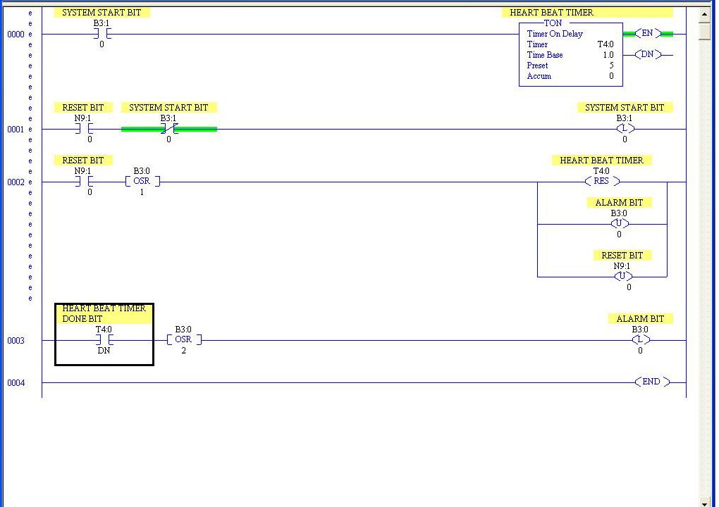
One of the ways I do it is below. In this example let’s say that I need to write a value to “N9:0”. In the message instruction that is writing to this PLC I set “N9:0” as the data table address I’m writing to but I write two words (two elements) so that I’m also writing to “N9:1”. In the data table that I’m getting the data from (in the PLC with the message instruction) the word that will go to “N9:1” has bit “0” set to “1” so that in this PLC when the message instruction is accepted “N9:1/0” will go high (go to “1”). If it’s the first time the message instruction has been executed then rung 1 will use “N9:1/0” to latch bit “B3:1/0” which starts the process by enabling the timer and in rung 2, among other things, “N9:1/0” is unlatched. After that every time when “N9:1/0” goes high it resets the timer and unlatches itself. That way every time the message instruction gets through it should set “N9:1/0” high resetting the timer. If the timer goes done (in this case after five seconds) then a bit is set that can be used to set off an alarm, stop a process, etc… Also in this example if the timer goes done but then the message instruction starts being received again the alarm bit is unlatched as is the timer so the system continues.
The other thing you can do with this method is to add a timer that measures how long there is an alarm condition and a counter to count how many times it happens. I’ve done that where I knew I was dropping communications and wanted to see how many times over a given period of time and how long the average outage was.


HEARTBEAT_LITE%20copy_zpsz8ucjez2.jpg
 
I typically just use a heartbeat bit that toggles on and off, and a timer to see if it stops changing. There are ups and downs to every method, but I've found this one to be the simplest and easiest to monitor.

If you're using RSlogix 5000 you dont' even need to create the heartbeat, you can just use one of the bits from the free running clock. The biggest gotcha in this one is that if your message update rate syncs with your toggling frequency, you'll never see the change - so if your message update is 1s, don't use a 500ms/500ms toggle :)

Screen Shot 2015-09-29 at 8.28.25 am.png
 
ASF,

I modified your code a little & it works exactly as I want. Nice and simple. And I changed the timer to .01 seconds so I can see some increment between the 1 second messages.

Capture.jpg
 
Not sure if I'm seeing the whole picture here...but I'm seeing a couple of things there that are a little "off"...

I'm assuming that N20:20/15 is your "external system running" bit, which is written to by a MSG instruction, either in this processor or an external one? Do you need to use this bit anywhere else in the code? Is this bit a "flasher", or just an "on when running, off when stopped" bit?
 
Bit N20:20/15 is only set to 1 from a message from the 5/05. It is not used anywhere else on either PLC's - just to reset the timer when it is written again on a successful message. The bit is always ON on the 5/05 & after it resets the timer the 5/04 turns it off on itself only, to be off for the next message OSR. All messaging is done by the 5/05.

I forced the bit OFF on the 5/05 as a test & the 5/04 timed out promptly & dropped my Current bit and the Current bit came back on as soon as I set the bit on the 5/05 again.

Then I added a cascading set of counters to count how many times the Current bit dropped and a RTO with cascading counters to log how long the Current bit has been off.
 
Last edited:
Ah yes, good stuff. You seem to have thought of most of the things I was worried about (is the bit being used anywhere else in the code, etc).

Still one thing I'm uneasy about though - not 100% sure if it would be an issue or not, but here's where I'm coming from...

Let's say you were using the RSLogix 5000 platform, and transferring the data with produced/consumed tags. Produced/Consumed tags are transferred even if neither PLC is in run mode. So if your remote PLC faults, the remote bit (produced tag) is still a "1", and your local PLC will read that "1" and write a "1" to your local bit (consumed tag) accordingly. You can probably see where I'm going with this. In your case, if your MSG instruction is in your remote PLC, and writing to N20:20/15 in your local PLC, no problem. If the remote PLC faults or otherwise stops executing code, then it will stop overwriting N20:20/15 and your timer will time out. But if your MSG instruction is in your local PLC, and you're reading from your remote PLC, then it *might* be possible that even when the remote PLC is faulted or otherwise not in run mode - but still online - that your local MSG instruction can still look at it and see that N20:20/15 is still 1. Even if you think that "well, it only turns that bit on if the PLC is running" - not necessarily. If the PLC faults, everything stays right where it is, and it's not until the prescan sweep that happens just before it goes back to run mode that these sort of things are reset.

I'm not 100% certain whether this would be the case or not, but if it were me, I'd be testing it out :)

Just one other small note for future use - because you're using a MSG instruction to transfer the data, which you can schedule and control in sync with the rest of the ladder logic, all of this works fine. On the other hand, if you were getting the data from a produced/consumed tag or another RPI-based ethernet device, then it's important to remember that the communication wizardry happens completely independent of and asynchronously to your ladder logic. So that N20:20/15 could be unexpectedly changed halfway through one of those rungs. I can't see it causing any dramas in this case but worth remembering :)
 
The bit is sent by the remote PLC, not read by the local PLC, so it only gets sent if the remote is running.

But I just thought - I'm going to see if I can MSG the processor status S:1, then check if bits 1 & 2 are on (running for a SLC) on the other - when the PLC faults or goes into program mode it would still have the current bit ON, until the prescan; just to make certain the wrong info doesn't get messaged.

I just tried it & the 5/05 processor status is getting sent to N20:100 on the 5/04, so If I check if bits /1 & /2 are ON, then the 5/05 is in run mode, not program or faulted.

And I just checked the log on the watchdog of the 5/04 & it shows I lost comm's once overnight for over 8 seconds for 1 minute 33. 76 seconds.
 
Last edited:

Similar Topics

I have a redundant ControlLogix being set up. This program reads a value from a remote site which happens to be SLC PLC. Rockwell mentions SLC...
Replies
2
Views
110
Hello, I have a ControlLogix redundant controller being set up. The program reads a value from a remote site which hosts a SLC PLC. Rockwell...
Replies
0
Views
94
A new Forum member resurrected an old post with a variation that I think should be done in a new thread to get the best attention and advice...
Replies
11
Views
2,398
Good morning, I’m looking for assistance on what hardware is needed to message from a CompactLogix L3 controller to a SLC 5/03 or 5/04 via serial...
Replies
2
Views
1,341
I ran across the following lines of code and I had a couple of questions. Keep in mind I'm fairly new and trying to understand the hows and why's...
Replies
6
Views
2,137
Back
Top Bottom