Slc500 analog input status word problem

govoni

Member
Join Date
Jan 2009
Location
USA
Posts
6
Today while tracking down a 4-20 mA loop problem for old project since 2005.

mA for loop is OK but channel give me -1 on scada

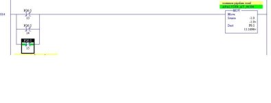
i found rung depend on status bit 15 energized move -1 to reading
please show attachment

and please help me how to solve this problem the configuration is OK and work for all channels

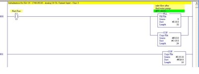
staus bit 15 problem.JPG initialization for slot 18 AI.JPG
 
project work sience year 2005

First thank you for your response.
i check the configuration word and the project work without problems sience year 2005 and configuration data file is correct
please see data file attached

data file.JPG
 
Have you tryed to disable channel 5 as that seems to be the one that is giving you trouble. Then re-enabling it and see if the status changes? The manual says that the error code clear when you go from disable to enable. Might work.
 
Since this is slot 18, one must ask may this slot be power cycled without triggering the first scan bit?

We recently tested the addition of some remote analog inputs that are subject to separate lockout procedures, and had to add code to trigger the configuration based on the slot status in parallel with the First Scan bit.

It doesn't make sense to constantly write the configuration which some people do, and you can wait until you see a mismatch when reading the configuration before enabling the slot, and it might be as simple as a flaky analog card that wipes out its own settings after warming up...but a config. error is a config error, put a manual configuration write bit in parallel ad trigger it manually, see that the card does not fault, the data remain intact, then you have proof of good config. data. and can put that to bed.
 
mA for loop is OK but channel give me -1 on scada
Where is this "-1 on scada"? If you are talking about your Rung 14, then when N26:5/15 is OFF or 0, then a -1 will be moved to F8:5. Now what controls N26:5/15? Are these 3 bits N26:5/13, /14, and /15 supposed to be the configuration error bits for your analog input channel, or what? Why is your program moving a -1 to F8:5 if you want F8:5 instead to be your analog input? Is this a error-handling routine? If so, you may not need it at all because your configuration in N10:0 is for a Class 3 configuration, not a Class 1.

Bits 1 and 0 are only used in Class 1 mode. If these bits are set while
in Class 3 mode, a configuration error is set in the status word (bits 15, 14, and 13 set to 0, 1, and 1). The use of these bits is not necessary in Class 3 because Class 3 allows for data transfer of a 32-word block.
THESE BITS 13, 14, & 15 of the analog configuration word SHOULD BE SET TO OTHER THAN 0,0,0 ONLY WHEN USING THE OLD CLASS 1 CONFIGURATION. If using the newer Class 3, then bits 13, 14, & 15 should each always be 0!

Note that your Rung 14 is doing the -1 move when there is a 0 in any bit 13, 14, or 15. For a Class 3 setup (which I think you have as shown by N10:0) there should ALWAYS be a 0 in all 3 positions!

To help you more, we need to see the rungs that sets the values of N26:5/13, /14, and /15, and know what these 3 bits are really.
 
Last edited:

Similar Topics

I cannot add SLC500 analog input tag (I: 8.3) to EZSeries Touch Panel Editor (V 5.3). I used all the listed tag datatype but it all says "Invalid...
Replies
10
Views
259
Haven't done much with Analog inputs before. Need to read pressure input 10x a second and save last 10 seconds worth and then calculate avg for...
Replies
3
Views
2,145
I have a SLC500 5/05 and we have an alarm setup to monitor the status of the Analog Inputs we have wired to a 1746-NI8. We are using 5 of the...
Replies
14
Views
2,814
Hi, Sorry for my bad english, I'm from Poland. I've decided to learn basic PLC programming as hobby and to maybe get a better job. I have...
Replies
2
Views
1,337
Hello all, I'm having an issue displaying the value I'm getting from a PFC to display on my Red Lion G307..... and before anyone says it...I...
Replies
1
Views
2,131
Back
Top Bottom