Studio 5000 mapping selected inputs to array

Roddyw

Member
Join Date
Feb 2019
Location
SLC, UT
Posts
5
Hi,

I trying to figure, how to map local inputs to an array.

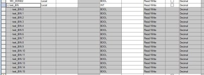
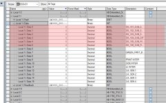
I've attaches some images; the FROM image has the the local inputs (from 0 to 5 only) that I would like to map. The TO image has the "destination array" of the selected inputs.

In a nutshell, I have a Fanuc controller wire to the input of compact logix; the controller has a max of 8 output channels (wire to the plc inputs) but I need more I/O to communicate with the Fanuc controller... hopefully this makes sense.

I do remember doing this in the past, but I think I may be confusing software platforms.

Thank you,
FROM.JPG TO.JPG
 
Your "FROM" image shows you have 6 digital inputs (0 to 5) that are part(the 1st 6 bits) of an INT in your input card tag.

Your "TO" image shows an array of 6 DINTS.

your Robot controller has 8 Digital outputs that are directly wired to the PLCs input card?

I'm confused as to what you are trying to accomplish with the array.


anyway the "COP" copy instruction should move the data for you or you could do individual bits if you don't want the other data to come too.

the "MVM" masked move would only move selected bits.

the 6 or 8 bits will fit in a single DINT so you don't need an array at all.

essentially this will buffer your input data into another tag, none of that will give you "more" I/O

maybe I'm misunderstanding what you are trying to do
 
I'm trying to binarize the inputs to a decimal. (i.e 101001 = 42)

2^6 (6 being the number of inputs) would give 64 possible combinations that I can use as output/inputs for the robot. those 8 were the initial wiring, I'm only planning to use 6--I don't need 2^8 possible combinations.

I was aware that I could do it on the rungs, but I was hoping the there was a "cleaner" way to do it like aliasing or something alike.

Yeah, sorry I'm from Spain, so my English Today might be slight off.

THX
 
If your goal is to end up with a decimal number, then I would suggest using the MVM instruction where Source A is the whole input word (Local:1.Data), the Mask is 63 (six ones), and the destination is your tag to hold the value being sent by the robot. It might be wise to CLR the destination value initially (only needs to happen once) to ensure that none of the higher bits are set since the MVM instruction will "leave alone" any bits in position 7 or higher.
 
It doesn't seems to be working--this is the part where I drop the ball. I'm using 2^4 (16) just for the test, so the 1111 (15) should be the mask, right?

I see the change of values when I monitor the local.data tag, but I don's see that change on the MVM rung block (underneath source 2#000_0000_....)

c01.JPG c02.JPG
 
It looks like your data is all zeros, but we can't see all of it. Those zeros are passing through the mask where the bit position contains a '1' and the result is also all zeros. (I am assuming the MVM is being scanned and your result is the same when on-line, but it looks like the screenshot is not on-line).

See if you can get a screenshot of the data in decimal coming into the MVM. Make sure the MVM is on a true rung that is being scanned.
 
I'm trying to binarize the inputs to a decimal. (i.e 101001 = 42)

2^6 (6 being the number of inputs) would give 64 possible combinations that I can use as output/inputs for the robot. those 8 were the initial wiring, I'm only planning to use 6--I don't need 2^8 possible combinations.

I was aware that I could do it on the rungs, but I was hoping the there was a "cleaner" way to do it like aliasing or something alike.

Yeah, sorry I'm from Spain, so my English Today might be slight off.

THX

You can do an "Alias". Select the Tag you want to be connected to the inputs (in edit mode) highlight the "Alias For" box, use the pull down button and select your "Local:1: Data" Tag from the list. Then when the inputs change the Tag you setup will change with them. By the way, "101001" = 41 (which is 42 different combinations to be fair).
 
Last edited:
It doesn't seems to be working--this is the part where I drop the ball. I'm using 2^4 (16) just for the test, so the 1111 (15) should be the mask, right?

If you want to pass 2^4, your mask needs to be 31 (2^5 - 1).

Personally, I prefer a bitwise AND instruction for these types of data moves.
 
It looks like your data is all zeros, but we can't see all of it. Those zeros are passing through the mask where the bit position contains a '1' and the result is also all zeros. (I am assuming the MVM is being scanned and your result is the same when on-line, but it looks like the screenshot is not on-line).

See if you can get a screenshot of the data in decimal coming into the MVM. Make sure the MVM is on a true rung that is being scanned.

Yeah, it forgot to put the PLC in run mode o_O

...it's all good now.
 

Similar Topics

Hi all, New to the forums and wanted to ask you guys a preferential question. With the newer versions of Studio you have various options on how...
Replies
9
Views
3,798
Hi Everyone. Not posted on here for a long time, but I am hoping someone can help me. I am doing a differential pressure calculation in a L27ERM...
Replies
15
Views
267
Hi, how do I convert 2x Integer registers to a Real? The two integers are from Modbus registers that contain a floating point value, I need to...
Replies
2
Views
121
What is the best way to extract the hour and minute from the register that comes from Yaskawa VFD. In studio 5000 I have a register saved as INT...
Replies
3
Views
125
I have an Allen Bradley temperature switch that I am trying to use in studio 5000. I am getting the message "Unable to interpret the IODD file"...
Replies
0
Views
76
Back
Top Bottom