Thumbwheel Timer Countdown

toljoe

Member
Join Date
Dec 2020
Location
Toledo, OH
Posts
5
So I'm fairly new to PLC programing. in my PLC class my task right now is to write some logic that uses a thumbwheel to set the timer thats displayed on a display unit. Starts on a pushbutton and stops at Zero. With COVID these type of classes have sucked to learn from home for me any help would be great.
 
what environment (RaspberryPI/CodeSys, Siemens, Allen-Bradley, web emulator)?


what language (Structured Text, Ladder, Function Block, Python, AWK, C/C++, Fortran)?


is it a physical thumbwheel, or a virtual thumbwheel on an HMI? how are the values input to the PLC? how is the start button implemented, HMI, discrete input, something else?


how many thumbwheels (digits)? what radix?


most timers count up; does the program need to calculate and/or show a number counting down to zero? if yes, how many decimal places? Are integer or decimal fraction seconds ok? how many decimal places? or should the display be HH:MM:SS (hours:minutes:seconds)?

does the PLC have a timer instruction? if yes, what is its resolution (ms,cs,s)?

are you doing this for yourself or for a class?


what is your background and general skill set? are you comfortable with the concepts of numbers, bits and Boolean logic, radix, 16- and 32-bit binary, integer and floatin-point values, discrete inputs and outputs, contacts and coils, how plc cycles work (i/o, scan, communications, etc.), programming in any other languages?


show us what have you done so far. if it's a class, then it would be a disservice to you for someone on the forum to do the work, but someone will help you along.

all programming, PLC or otherwise, boils down to creating a digital model, within the PLC in this case, of something in the real world. the only real decision is the fidelity of the model; everything else follows from that. the program will allocate entities (for example, a 16-bit integer to represent seconds remaining in a running timer, and a timer instruction to implement the timing function, inputs to represent the thumbwheels and the timer start button, output to turn on a light or sound a buzzer when the timer expires), and then manipulates some of those entities in response to changes in other entities.

welcome to the forum!
 
Last edited:
On of the most useful things I have found, beyond this forum, are the Flow Chart for each instruction in the Allen-Bradley manuals e.g. see https://literature.rockwellautomation.com/idc/groups/literature/documents/rm/1756-rm003_-en-p.pdf#%5B%7B%22num%22%3A377%2C%22gen%22%3A0%7D%2C%7B%22name%22%3A%22XYZ%22%7D%2C45%2C191%2C0%5D; the other pieces are also helpful (e.g. the plots of the bits and numbers in the Description section). Because the most used instructions are common across all brands, these are also generally useful for learning on non-A-B hardware.


By understanding the details how an instruction works e.g. the meaning and behavior of the .CU, .EN and .ACC parameters of the counter structure for the CTU instruction, I get an idea how that instruction can be used (and abused;)).


Jargon/vocabulary will be a major hurdle. E.g. what does one-shot mean; what is rising-edge, false-to-true transition, 0-to-1 transition? As with any language, that will take time, but feel free to ask for a definition of, or clarification of, any term you do not immediately understand.


IMNSHO, everyone who wants to program PLCs should spend the 94m34s it takes to view Ron Beaufort's excellent series here. The sections where Ron walks and talks (and probably chews gum;)) through rungs of logic are alone worth the price of admission; having that skill in the toolbox is an absolute necessity for any programmer or troubleshooter.
 
Last edited:
So this is for class (PLC1) and we got a simulator that is based like RSLogix 500 and the program name is PLC500. So like i said before because of COVID this has been basically a read and figure it out yourself type class, unfortunately i don't learn this way. I'm more of a watch you do it or we go through steps together type way. The book we had to get for the class is https://www.amazon.com/Programmable-Logic-Controllers-Frank-Petruzella/dp/007337384

Simpic.PNG
 
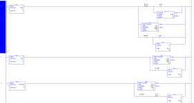
I'm fairly new but not totally unexperienced. From some reason i feel like i have a "writers block" type thing going on. this is one of the other questions i did.

Final Num12.PNG
 
So....you have a BCD input and a BCD display. These will be used to enter the time and display remaining time. Pick some input to start the logic. Everything else will be internal.
 
Some years since I used AB software (another story) but there are a number of things to consider, I will leave any suggestions of code to others here.
First it depends on how the timer gets it's timing data for example some PLC's use integers, some BCD etc.
So first determine the type of pre-set for the timer.
BCD to integer conversion?
Or use the BCD direct.
For example convert the BCD value from the I/O to an integer and store it in a register then use the register in the timer pre-set.
As many timers may be 10 or 100ms time base you may need to multiply your converted BCD by 10 or 100 etc. depending on the time delay you need i.e. 0.1 seconds units or 1 second units etc.
IEC Timers are function blocks and the pre-set is normally shown as T#1s (1 second = 1000ms) the timers are often either 10ms or 100ms (0.01 or 0.1 sec.) The IEC function increments the timer value by either 10 or 100 .
Not sure this applies to all platforms but something to be aware of in IEC types.
So for example a 3 digit BCD 0-999 but if the timer base is 100ms then converting it to an integer would give you 0-99.9 seconds, so if you want 0-999 seconds then you would need to multiply it value by 10.

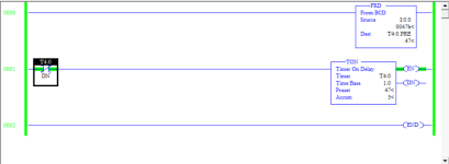
Timer.png
 
SI'm more of a watch you do it or we go through steps together type way.
Simpic.PNG


Let's reverse it slightly, you do something and then post it here, say what you want it to do, what it actually does*, and if the two are different then why you think that is so, and ask for comments and suggestions.


TL;DR


* "The only thing worse than a program not doing what I want it to do is when it does exactly what I told it to do."


Because the first thing I as a learning programmer needs to fix in my mind with absolute certainty is that I have to get stupid, as stupid as the computer. Because it does not matter a whit what I want the computer to do, it only matters what I tell it to do. I have spent over forty years doing this and I have found only one compiler bug, and I was surprised when I found that one. Whenever the computer is not doing what I want, I always look at my code and think like the computer; sometimes it takes a few seconds, sometimes a few days, sometimes it takes a whole 'nuther project of debugging and monitoring code to what the bits are doing, but I have only once been disappointed with the assumption that the mistake was in my code.


Your preferred approach for learning is fine for this task, but there is not a back and forth in this forum format, so how are you going to write the next program?

What I can tell you is what I already said, that the pieces of the program compose a model for the pieces of the world it is modeling. If you are blocked by the whole problem, take a small piece of it, and code that up. Then take another piece and code that up. Sometimes one piece of code interacts with another piece, so the previous pieces needs to be modified, or perhaps even completely rewritten using a different approach.

E.g start a timer TON an input becomes 1: that can be done on one rung:

  • your previous example shows you know how to do that,
  • and parky has also given an example of that;
  • don't worry about the duration of the TON
    • and instead set it for five seconds,
    • you can fix that later
Now that it's coded:

  • run it on the PLC500 emulator,
  • watch what happens to the bits of the TON instruction,
  • compare what you see with the flow charts and descriptions in the logix 5000 manual; memorize every piece of that behavior (.TT, .EN, .DN, .ACC etc.), because it will never change.
I am not trying to be snarky or difficult here, but you aspire to become part of an industry that controls and moves heavy objects; it would be irresponsible of the folks on this forum to do the work for you.


Did you watch Ron's videos? Personally, I get such a feeling of peace and security every time he utters the phrase "look for a 1."


Another great and simple resource is Patterns of Ladder Logic Programming; we all use those over and over.


And here is summat for nought. You showed some of your code from a previous exercise, and the first rung looked like this:
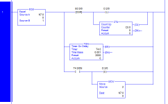

xxx.png


Would you be surprised that it could be coded a bit more simply:
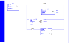
yyy.png


N.B. It might be a bit better make the [OTE O:2/0] be the last branch, after the [XIC T4:0/DN MOV 2 N8:0] branch.


N.B. This assumes the rung 1 is the only rung that changes N7:0 from 1 to something else.


N.B. There are some subtle differences in edge cases, but for the bulk of operations the behavior of both rungs will be the same.


So, what was my first clue that that could be simplified? The ONS (One-shot instruction) feeding the OTL (latch) and CTU (count-up) instructions.

  1. A latch instruction does not need a one-shot in front of it; when the logic feeding the latch goes from false-to-true the output is assigned a 1, and that 1 stays there until another output removes it.
  2. A count-up instruction maintains it's own rising-edge detector (see the behavior of bit C5:0/CU in the CTU flow charts; it is equivalent to the B3:0/0 in your ONS).
 
Last edited:
IF - your environment is SLC500 (including the MicroLogix range)....

AND IF - you are using a hardware thumbwheel switch connected to four inputs ....

THEN - you MUST put an OTU S:5/0 as the last rung of program file 2.

Let me explain. Somewhere in your code you will be reading the thumbwheel switch, and will be using an FRD (From BCD) instruction (because thumbwheel switches are encoded as BCD).

This should give you a base 10 value of the switch position.

But as you move through the digits on your BCD encoded thumbwheel switch, you will invariably present to the inputs an "illegal" bit pattern, i.e. not an interpretation of the digits 0-9 (since the switch has 4 bits, it can give bit patterns of the HEX digits A-F).

On the SLC platform (alone, but that includes all of the MicroLocix hardware) that will generate an "overflow" status, BUT will also set the "Overflow Trap" bit S:5/0. That bit being set at the end of the scan will put the processor into major fault.

It is useless.... there is no information recorded as to where the overflow occurred, it just says "somewhere we had an overflow, so shut down". Hardly user-friendly !!

None of the other A-B platforms have it, so I just don't see the point of it. If you do anything in your application that you need to worry about math overflow, you should inspect the status bits immediately afterwards, and deal with the consequences.

Nearly every Logix500 program I have ever seen has OTU S:5/0 as an unconditional rung at the end of file 2
 
You can buy BCD switches that only give 0-9 so this will never occur, however, What I should have done is masked the bits so only the number of digits i.e. 3 places = 12 bits or it will put an illegal value in the timer, this means the other 4 inputs could be used for other purposes. But I do agree in resetting the error bit when coding even if temporarily and setting another bit so that could be monitored to check for those errors then perhaps find where the code generates the error and try to correct rather than just leave the code to reset the error bit.
 
You can buy BCD switches that only give 0-9 so this will never occur,

Most BCD thumbwheel switches only go 0-9, the ones with A-F as well are "specialised" and way more expensive.

The problem will still occur on the 0-9 devices, I know this for a fact having demonstrated it dozens of times in class.

The switches have a rotating structure with "fingers" making contact with "lands" on the PCB. Unless the PCB is double-sided (and most of the ones you buy aren't), there will always be positions where the fingers are moving between codes, and possibly picking up the PCB tracks to lands.

The thumbwheel switches on the RA training rigs (I believe "Cherry" manufacture) give a "non-decimal" bit pattern as you move the thumbwheel between "2" and "3". Without unlatching the Overflow Trap bit, as you traverse that part of the PCB, it will almost always major fault an SLC.

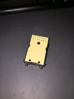
EDIT : I have just photographed one of my thumbweel switches (These are pushbutton detent operation, but the effect is the same, the buttons turn the "wheel" one way or the other, same as a "thumbwheel". You can clearly see the tracks through the PCB which connect to the edge connectors. As the fingers move over those tracks, illegal BCD codes can be generated.

2020-12-13_145030.jpg
 
Last edited:
Hm... Interesting, I worked on a SLC500 that had 4 banks of 3 thumbwheel switches (not my build but done by another company) we did a mod on it and I know the O/F bit was not in the reset in the code as I managed to fault the PLC on one, this was my code causing the problem not the existing and they never had a problem in the previous 12 years I seem to remember these were the pushbutton types but have no idea of the make, these also used the BCD to Dec conversion, talk about coincidence I was talking to the guy who was engineering manager on that plant only yesterday.
 
Hm... Interesting, I worked on a SLC500 that had 4 banks of 3 thumbwheel switches (not my build but done by another company) we did a mod on it and I know the O/F bit was not in the reset in the code as I managed to fault the PLC on one, this was my code causing the problem not the existing and they never had a problem in the previous 12 years I seem to remember these were the pushbutton types but have no idea of the make, these also used the BCD to Dec conversion, talk about coincidence I was talking to the guy who was engineering manager on that plant only yesterday.

The whole problem can go away if you make the switches with double-side PCBs, but damn near every one I've ever seen uses single sided, like the one I photographed.

Here's another one, this time an Omron - same single-side PCB, but this one isn't translucent ... but you know them traces are weaving between the landing pads.

What the SLC FRD instruction does when it sees a non-BCD bit pattern, is set the overflow status bit AND the overflow trap bit, and puts 32767 into the destination integer !

Conversely, a Logix5000 CPU will interpret the bit pattern as a 4-bit HEX value, and if you put all 4 bits on, you will get 15 in the destination !! So it's not FRD (FRom bcD) at all, but "From Hex".... !!

2020-12-13 16.30.21.jpg 2020-12-13 16.30.57.jpg 2020-12-13_164609.jpg
 

Similar Topics

Hello all, Though no stranger to computers and programming, I am a newbie to PLCs. I have a simple task but am not sure how to connect the dots...
Replies
7
Views
2,331
1. The first thumbwheel stuck, only able to switch between 0 and 9. It can go from 000-099 or 900-999. 2. If I set it to 009, I can ping to...
Replies
3
Views
2,036
hi, guys. I am using the Siemens setp 7. I have a thumbwheel input in the panel, which has four bit input all boolean ones? How can I get the...
Replies
17
Views
4,568
How many wiring terminals are their on a 3 digit thumbwheel switch? I've read some notes that a two digit switch has for the LSD 5 terminals and...
Replies
1
Views
1,672
Hi all, I am looking for a BCD or hex thumbwheel switch. I only plan to use 0-7 (3 bits). I prefer something that has leads already. I would...
Replies
6
Views
2,745
Back
Top Bottom