Powerflex 700 Torque Control Tuning

Can you follow the commanded torque to see more information about the torque regulator? It would be interesting to see more about what the drive thinks the actual torque is, what it is doing as far as commands/etc.
 
Commanded torque feeds into the Current Loop:

current-loop.png
 
Okay - I noticed during the cycling that the "Observe STS" bit turns on and off with each cycle. Par 440 "Control Status" is described as "Displays a summary status of any condition that can be limiting either the current or the torque reference"

"Observe STS" is off when stopped and on when running steady state. I can't find any info on what it means though.
 
Seems to be a physical harmonic, having to do with roll/web/whatever inertia and any "elasticity" in the system, whether that elasticity is physical (web) or control.

What is the equivalent of a capacitor or an inductor in web handling?

My dad had a Fiat 124 Sport Coupe, it was a gorgeous piece of rust bucket (upstate New York). At a certain speed in second gear with the gas pedal held just so, the engine would surge and ebb to the point of eliciting chirps from the tire-pavement interface. Used to crack my friends and me up as we drove home from rock concerts at SPAC in our then "state of mind" ;).
 
Continuing to dig, found info on Observe STS - it's high motor slip:
https://rockwellautomation.custhelp.com/app/answers/answer_view/a_id/33828/loc/en_US#__highlight

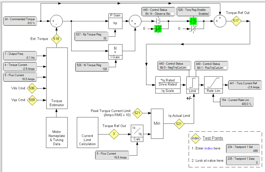
Parameter 440 (Control Status), bit 14 (Observe Status) bit activates based on the value of parameter 121 (Slip RPM) meaning that this bit will go active if the value of the motor slip goes above or below a set range. The range the bit monitors is between 1/2 the value of the number in that parameter for the minimum setting and 2x the value of the number for the maximum.

If the feedback mode is open loop, but you are trying to hold torque at zero speed, this bit will toggle causing the torque to go away and come back, over and over.

Example:

If your Slip Rpm (par. 121) has a value of 10, then the window that parameter 440 bit 14 monitors will be between 5 and 20 rpm. If the slip goes beyond that window then the bit will go active. Along with the Min slip (bit 8) or Max slip (bit 9) based on which condition is true..

Parameter 121= 10 RPM

Min range Setting= 5 (Par 121 / 2 )

Max range Setting= 20 (2 * Par 121)

Par 121 is set to 17.4rpm, so the bit will go true if I'm within 8 - 34rpm of my desired speed. The fact that the bit is going false during oscillations tells me that the drive thinks it is out of control.

Think it's worth running an autotune? That would also affect the inertia value, which is included in the Torque Reg control calculation.
 
I'm kind of with drbitboy on this one. Although I am more sold on a mechanical oscillation than he may be.

Try to tie the period of oscillation to roll revolutions. The easiest way to do this that I know of is calculate the diameter that would give you one revolution in one oscillation period. Then look for rotating items of that diameter.

Another thing to do is remove the material from around the load cell roll and hit the load cell roll with a dead blow hammer in the load cell force measurement direction while trending the tension feedback. If you are effectively measuring 3200lb hitting the roll a deadblow hammer won't hurt anything. See if the oscillation period you record is the same as the tension oscillation you see when running. If so, the cause is likely a cyclic force in the web that matches up with the natural frequency of the load cell roll system. Look for idler rolls with missing balance weights, idler rolls that turn hard in a portion of their revolution due to bad bearings or anything else that would put a tension pulse into the web at that frequency.

The place I have seen this is the past is on dead shaft load cell idler rolls that have particularly long idler roll shafts. However, I have never seen this happen at such slow speeds. If it is load cell roll oscillation then the roll must be really heavy and the shaft must be particularly small diameter. The deadblow test will tell you if this is the culprit. As for why it suddenly decided to start happening now? that's a tougher question.

Keith
 
I agree with the oscillation theory. That is why I was asking about how the material goes around the rollers but I thought it might be due to a slip/stick problem. The results would be similar especially at low speeds where the stiction is highest. One way to stop oscillations is to add damping/friction but not the kind that causes slip stick. This is like adding a resistor to drbitboys RL circuit.


A more complicated way of handling this is using electronic damping. Perhaps there is an extra feedback that goes to the torque motor control that can use the oscillations as feed back or damping.


I don't like the way the torque was changed in a step in on of the plots above. That is a sure way to excite an oscillating system. The frequency of acceleration needs to be below the natural frequency by a significant amount.
 
We once had a very similar issue, running paper web w/bad vibration at certain speed. Turned out to be bad bearings on the web guide rollers.
 
I'm kind of with drbitboy on this one. Although I am more sold on a mechanical oscillation than he may be.

I think we're all familiar with maintenance blaming controls for a mechanical issue until the controls people prove it's a mechanical issue. ;)

Try to tie the period of oscillation to roll revolutions. The easiest way to do this that I know of is calculate the diameter that would give you one revolution in one oscillation period. Then look for rotating items of that diameter.

Okay, so oscillations happen between 13-24ypm and have a period of 2 seconds. That means I'm looking for a roll diameter of 5-9", which is pretty spot on for what's in the area.
 
I apologize for the stupid question.

How is speed regulated?

Before this tension control motor is a compensator, after it is the main motor for the line which regulates line speed. There is no speed regulation in this drive whatsoever, it purely maintains tension in the zone between the compensator and main motor. This drive's output RPM is just a function of the speed required to maintain measured torque. Rockwell's torque control documentation is extremely sparse - everything I've found on it I've put in this thread, and most of it I've found by guessing and digging.
 
Here's the web path. The pull roll is coupled to the motor, the coated roll is connected to the pull roll via a chain drive.

pretension-threading.png
 
I'm so silly and lazy
May I please you to explain #8 Purple, Yellow and Orange curves?

Purple is overall web speed.
Yellow is the O.TorqueSetpoint1 signal from PLC to drive.
Orange is the motor current feedback from the drive - each step is 0.1A.

The trend in post #8 was pulled from Historian and not captured live within Studio 5000, so the resolution and scaling are a bit different from the earlier trends.
 

Similar Topics

Hello, I am currently in the final week of my internship and I have encountered issues with communication between a PowerFlex 700 variable...
Replies
8
Views
216
I've got a Powerflex 700 that doesn't like to get going in the mornings. This motor will run anywhere from 30 seconds to 5 minutes before it just...
Replies
3
Views
201
Looking for some assistance. I am very familiar with Yaskawa VFDs, but not so much with AB VFDs. I am working on some hardwired AB PowerFlex 700...
Replies
2
Views
158
Can someone with Drive Executive please save me a printout of the parameters for this drive in this file. I'm in a bind and would greatly...
Replies
2
Views
374
Hello all, I was forced to replace a Powerflex 700 to a Powerflex 70 due to what is available. The digital input parameters (361-366) have a...
Replies
1
Views
499
Back
Top Bottom