Beckhoff TC2.11 B1545 Modbus TCP Questions

jjensen

Member
Join Date
Mar 2016
Location
Pittsburg
Posts
8
Hello
Long time lurker. I am flailing around trying to figure out how to implement MODBUS TCP on a W2000 IPC that controls one of my company's grinder. I am lucky enough that I have a spare IPC (k550spare) to test and learn MODBUS TCP. I am just not understanding some very very very basic items about MODBUS TCP and TwinCAT. This is the only application in my plant that has TwinCAT,and the only application that uses MODBUS.


I do have the TwinCAT MODBUS TCP Server Configuration software installed and running on the same k550spare IPC.

I am trying to communication to three different devices via TCP. One is Alta Vibration IPC, second is Ignition HMI 8.x, and the third is IBA Data Recorder. I can test the Ignition HMI and the IBA MODBUS TCP connections. I know that I have some level of communication happening from k550spare to Ignition and IBA. Ignition states I do have a connection status, but Ignition is stating there are communication errors. IBA states the same condition. I can see the error counter climbing. I am using k550spare as the source of the data, Alta, Ignition, and IBA will only read values sourced from k550spare.


A question on screenshot attachment k550spare MODBUS TCP Server Question popup.gif; is the IP Address & Port entered here only the "Server IP & Port"? OR do I build a *.xml file that contains the addresses of all items on the MODBUS TCP? Second question on the screenshot; Does the *.xml configuration file contain ALL of the MODBUS TCP Variables? Is the MODBUS Address structure and memory map separate from k550spare?


I believe Alta, Ignition, and IBA are clients and are setup this way. I was thinking k550spare was the Server, but now I think k550spare is a client as well.


Any help is appreciated. I have had no luck using Beckhoff's website. I have been able to glean some info from other websites and manuals.
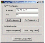
k550spare MODBUS TCP Server question popup.gif
 
Modbus TCP uses Clients (masters) and Servers (slaves).
So the image you have attached is a TwinCAT server. It will do nothing unless a client requests information.
Note: Port 502 is usually the default for Modbus TCP.

Regards,
 
TwinCAT can act as both a Modbus server (slave) and client (master). Since you showed the server configuration window, I'm assuming you want to use it as a server. In that case your other devices would have to be acting as clients.

It is not necessary to modify anything in the server configuration, other than the IP and port, unless you want to change the mapping. The default mapping should be fine unless you need to transfer tons of data.

https://infosys.beckhoff.com/englis...18014398702226955.html&id=4437939840240302211

The trick is, you have to define global array variables with specific names which are linked to the memory areas of the Modbus server. My experience is with TwinCAT 3, and on that platform I use GVL.mb_Output_Registers which is an array of 256 words and corresponds to the Modbus "holding registers" (prefix 4). I think the variable names might be slightly different in TC2. In the default mapping, GVL.mb_Output_Registers[0] corresponds to Modbus address 432768 (or possibly 432769 if the client has an offset) and so on. There are other Modbus memory areas you can use but I have found the holding area to be the most universally available on other devices.
 
Thanks for the feedback.

I do believe I want the TwinCAT to be the server (passive). The TwinCAT IPC has all of the information and is the grinder controller.

I used that screenshot because I am/was not sure what to post. I have tried the 'default configuration'; which caused both clients error feedback to go to 747d (invalid client timeout). At the moment I have shrunk my test to TwinCAT as server (192.168.165.168) and Ignition as client (192.168.52.115). Ignition shows a connection has been established but I am not able to pass any information. I see error code 0x04 (slave device failure)


So, I should *not* need to develop an *.xml file that contains the entire mapping and load into the Server configuration? Ok, that helps with all the different things I am trying.


I will look at the GVL.mb ADS areas. I know it is a couple of basic items I am missing with my lack of MODBUS experience.
 
Hello
I do have network connection communications from my beckhoff IPC to both the iba and Ignition HMI. But I am not able to pass information via Modbus to either programs.

I defined the four GVL.mb Arrays. I then reset the Beckhoff IPC Modbus configuration to default. The configuration file was different, it now had the GVL arrays and all of the associated addressing (decimal) and offsets. This Modbus configuration change was the necessary change that allowed good network communication to both the iba and Ignition. There are zero network communication errors.
The configuration file matches https://infosys.beckhoff.com/english.php?content=../content/1033/tcmodbussrv/html/tcmodbussrv_overview.htm&id=

I am now getting 0x707h General ADS errors in b_WriteError feedback (0x707 1799 device is not in a ready state).
I am not able to write to the #8000 Modbus address for either the Output Coils or Holding Registers at GVALs .mb_Output_Coils or .mb_Output_Registers.
WriteRegArray_iba_1(
sIPAddr:=RSIBA_ipaddr,
nTCPPort:= 502,
nUnitID:= 255,
nQuantity:= 20,
nMBAddr:= 16#8000,
cbLength:= SIZEOF(rArrayData_iba),
pSrcAddr:= ADR(rArrayData_iba),
bExecute:= iba_refresh_pulse,
tTimeout:= t#5s,
bBUSY=> b_WriteRegsBusy_iba,
bError=> b_WriteRegsError_iba,
nErrId=> n_WriteRegsErrorId_iba);

I don't know what I am missing.
 
It seems to me that you are mixing up the Modbus client and server functionality. On the server side, once you have the .mb_Output_Registers array variable set up, there's no other programming required. Whatever values you store in that array will be automatically linked with the Modbus server.

The function blocks like FB_mbWriteRegs are used when the Beckhoff device is acting as a client. (I'm assuming your WriteRegArray_iba_1 is an instance of this.) In that case the value of nMBAddr would be the Modbus address in the remote server that you are wanting to write (or read).

It is certainly possible to have the Beckhoff do both client and server simultaneously, but I question why you're using 16#8000 as your target address.
 
Thanks for the feedback. I have a better understanding now of the method to get the PLC values into an area where the Clients can access the information. I am finding the person who wrote the Modbus TCP code originally had the communication setup to a single client backwards. I think this is causing some of my major misunderstanding of how Modbus works. This PLC was originally setup as a Client and the ALTA was a Server. I was using the original code and trying to extrapolate out how to populate the Modbus area.
At this time I am using logic " mb_Output_Coils[0]:=TRUE;" as a test. But I am not seeing the value outside of TC. Now I need to learn how to properly define a Global.
 
So I am still stuck on the TC2.11 getting information out. I have the four arrays set up and I can see that TC2.11 is writing to the arrays. But the clients are not able to access the information.


Is there a need to define anything in TC2.11 configuration for Modbus TCP?


Is there a need to pulse, or set up the TC2.11 writes? Currently I have the writes occurring on every scan. Or is the TC2.11 writes occur when a client sends a request?
(*example*) Globals.mb_Output_Registers[5] := iba_wd_counter;


I am able to write to 40 001 +100 registers using Chipkin CAS Modbus Scanner with no issue. The two clients see the data no problem.
 
I am a bit confused, at first you say the clients are not able to access the server but at the bottom you say the clients see the data. Where is your Modbus utility writing the data to?

I only use TwinCAT 3 so I'm not familiar with variable naming in TC 2. Is it necessary to have the 'Globals' prefix on mb_Output_Registers? I only mention it because the explanation in the Infosys doesn't show a prefix.

Does your industrial PC have a firewall enabled? If so, you'll have to create an exception for the Modbus port.

modbus.JPG
 
I am going to physically move the Server (TC2.11) to the subnet (.117) tomorrow morning as a test. I am thinking that having the Server on the same subnet as one of the clients (iba) will test if there is a network issue.


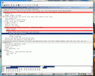
I was able to load a version of wireshark onto the Server PC. Wireshark reports back a Header checksum error when the Server responds to a request from the iba client. The header checksum feedback shows 0000 as the Server feedback (attached file). At this time this is the only thing that has shown any type of error feedback.


We did a tracert to the iba client from the Server PC. There were a total of two hops.


I am using the Chipkin CAS Modbus Scanner application to perform the FC16 write registers function as a test. This is how I was able to populate the first 100 Holding Registers. All the clients were able to read the values (iba, Ignition, Simply Modbus, and CAS). Only the TC was not able to access/read. I did create a FC3 function on TC to read the first 12 Holding Registers. The TC FC3 function is providing an ErrId of 745.


I was able to load a version of Simply Modbus onto the Server PC (TC2.11). The Simply Modbus application client was able to read the values in the first 100 holding registers to.

k550spare Modbus TCP global 4.gif
 
Hello
I believe I have Modbus TCP working now. There was a lot of learning on my side. I was also able to receive help from Beckhoff.
I properly defined GVL object under Resources/Global with the four arrays. The object/folder of GVL, with the exact name, is required for background configuration and data passing from the PLC/client to the Server. At least this is my limited understanding.o_O
I also removed all of my writes to GVL.mb_* array variables. I found out this was messing up the internal usage of the four arrays. My TC PLC was then able to read the Modbus values (Holding Registers) that I was able to populate with a Modbus TCP Server simulator. At this time I have my Modbus network sending and receiving Modbus TCP data.

thank you for the help.
 

Similar Topics

Hello all, I ran in to some trouble. I created 2 virtual machines to try out ADS communicating One machine is a PLC (TC2 32bit (runtime)), other...
Replies
3
Views
20,064
Hello all, I've got a problem with Alarm history display and saving to file, I tried to follow example on beckhoff site...
Replies
1
Views
1,868
Hi everyone, This is my first time posting, so please forgive any omissions or mistakes. I am attempting to control the velocity of a stepper...
Replies
18
Views
1,002
Hello sameone have Beckhoff PLC Siemens Sinamics V90 configuration example?
Replies
0
Views
98
hello, I am using Beckhoff with TwinCAT3 and when I change or add some new hardware or for any reason, there is a mismatch in the real hardware vs...
Replies
1
Views
126
Back
Top Bottom