Modicon Latch Question

desty

Member
Join Date
Feb 2011
Location
Montreal
Posts
36
Hi Guys,

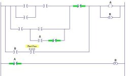
And I've come across another weird problem in the modicon, which is the Latch. How it is used and weirdly enough its not really a latch. In my case ive been rubbing my head how to convert this this into SLC5/05 rslogix 500. The way i thought is if i copy the latch instruction and do a whole rung of everything inverted to unlatch the coil, it seems a bit excessive and a bad way.

I'm not sure how to deal with the latches.

-Charles

ftkd9h.jpg
 
This is another one of those cases where you have to translate function, not language.

The modicon latch is also refered to as a memory retentive coil. You can select in your software whether it displays as a -(M)- or -(L)-. I prefer to use -(M)- to avoid confusion with the OTL as used in an AB PLC.

From the manual:
If a memory-retentive coil is ON at the time a PLC loses power, the coil will come back up in an ON state when power is restored. The coil will maintain that ON state for the first logic scan, and then the logic program will take control.

Looking at your network, 00067 is latched in on the bottom branch (this is the "logic program will take control" part). Looking at the network we can make a boolean statement for the conditions that will reset 00067: NOT 00222 AND 00064 AND NOT 00205.

Keep in mind that since we don't know what your process is that may not be adequate. You need to evaluate what 00067 does and how it needs to recover from a power failure and program it to do that rather than just translate the rung.

Edit to add:
Determining function and programming that rather than the ladder is crucial, because I can just about guarantee that you will have big problems on startup if you don't do this and merely just try to replicate the logic. <--- Having done a few of these I'm speaking with the voice of experience here. If you get stuck then write out a functions spec for that part of code and/or build a truth table, then program that from scratch using the spec you just created.
 
Last edited:
The L coil in 984 Ladder Logic (984LL) does not function the same as any Latch/Unlatch coil you are probably familiar with.

As I recall, a Latch, in 984LL, is used to determine the state of a coil when power is interrupted to the processor. If a latch coil is 'on' when power is lost, it will turn on for one scan when power is restored, after which it will respond to the logic in front of it.

Depending on the processor you are using (i.e. Quantum) the 94LL was enhanced with Sbit and Rbit functions, which act like a more typical latching coil.
 
Yes, I know how it works in the modicon, but in rslogix, using Latch/Unlatch seems a bit excessive. When the rung loses Power, output goes off, but when the controller loses power, output stays on for one scan unless conditions are still true..

im just wondering what is the easiest way to duplicate this.

Thanks.
 
I have to assume that the original programmer used a memory retentive coil for a reason. Thats where you have to determine why and what it does.

If you need it back on when power is restored then you are going to have to use OTL and OTU.
 
.....I know how it works in the modicon, but in rslogix, using Latch/Unlatch seems a bit excessive. When the rung loses Power, output goes off, but when the controller loses power, output stays on for one scan unless conditions are still true...

That is not a correct statement, or I read it wrong...

All A-B processors have 3 bit/bool output instructions that write to a single bit of memory. These are OTE, OTL, and OTU.

A "Pre-Scan" of all of the logic is performed at power-on, or a transition into RUN mode - the pre-scan affects non-retentive bit addresses.

OTE - during normal program scan, the associated address will be turned ON (written to a "1") by a rung that evaluates as TRUE, and turned OFF by a rung that evaluates as FALSE. In addition, bit addresses attached to OTE instructions will be automatically reset to zero during the processor pre-scan. Rung logic will therefore determine whether the bit address will be turned ON (true logic), or turned OFF (false logic). Addresses attached to OTE instructions are therefore "non-retentive".

OTL - during normal program scan, the associated address will be turned ON (written to a "1") by a rung that evaluates as TRUE. OTL will never write a "0" to the bit address. In addition, bit addresses attached to OTL instructions will not be automatically reset to zero during the processor pre-scan. Addresses attached to OTL instructions are therefore "retentive".

OTU - during normal program scan, the associated address will be turned OFF (written to a "0") by a rung that evaluates as TRUE. OTU will never write a "1" to the bit address. In addition, bit addresses attached to OTU instructions will not be automatically reset to zero during the processor pre-scan. Addresses attached to OTU instructions are therefore "retentive".

If a program has both retentive AND non-retentive instructions attached to the same bit address, then that address becomes non-retentive, since the pre-scan will reset it to "0".

HTH
 
You didnt read it wrong, I just made a mistake in Puctuation. My bad

I was talking about the Modicon and how the Latch works, Not the A-B Plc.
 
You could try something like this, but IMO it has a high "WTF factor" when someone else (or even yourself) comes along in a few years and tries to decipher what is happening.

I would try and determine what it needs to do and then program the function from scratch - you'll be happier with the end result.

a061411-011.JPG
 
Last edited:
remember too, Modicon logic is not scanned left to right, top to bottom,
but top left down to bottom right scanning down one column, then back up to the next column scanning down, etc.
 
Just don't forget that Modicon invented the programmable controller* which is how all this came to be. There is a massive installed base.


*(AB technically owns the term "PLC," but that is a semantics issue dealing with a trademark that eventually became the "Kleenex" of the controls world)
 
remember too, Modicon logic is not scanned left to right, top to bottom,
but top left down to bottom right scanning down one column, then back up to the next column scanning down, etc.

+1. We can't see rows 1 and 2 and 7 of that network, make sure there isn't something in there that completely changes how the rows we can see should be interpreted.
 
Hehe sorry guys, im just too young to know Modicon, so to me, when looking at other programs like Rslogix, Simantic manager,ect. this looks like "WTF" :D
 
+1. We can't see rows 1 and 2 and 7 of that network, make sure there isn't something in there that completely changes how the rows we can see should be interpreted.

Rung 1 and 2 aren't related, i looked before taking the screenshot.
 
Just don't forget that Modicon invented the programmable controller* which is how all this came to be. There is a massive installed base.


*(AB technically owns the term "PLC," but that is a semantics issue dealing with a trademark that eventually became the "Kleenex" of the controls world)

"Modicon invented the programmable controller" - actually it was invented by Bedford Associates, in response to a request by the hydramatic division of General Motors. They called it the "Modicon", then started a new company called Modicon to continue its development. Modicon was bought by Gould Electronics in 1977, then later by AEG, and is now in the hands of Schneider Electric (that's if wikipedia is up to date, lol).

The registered trade mark PLC lapsed many years ago, around the same time A-B redesigned and registered the trade-mark "SLC" - Small Logic Controller.

Over in the far east I hear rumours of a VVTLC - "Very Very Tiny Logic Controller - hehe
 

Similar Topics

Everything was working fine, but suddenly CPU went into error mode, and the ERR and TER LEDs lit up. Now I can't download or connect with the PLC...
Replies
0
Views
47
Hello All, Was hoping I could get a little help with Modicon ladder logic. This is the first time I have seen Modicon logic and currently trying...
Replies
6
Views
277
I have a 170AAO92100 card that I am interested in using as a 10 volt output. Is there setup that I have to do in order to change output or simply...
Replies
0
Views
87
Hi, Seeking consultation on an implementation matter, and have a question about Modicon Compact 984 communication through RS485: Three Modicon...
Replies
4
Views
231
After updating a panel, I inherited another PLC for my "learning lab". It's a Modicon TSX Micro. I've not worked with a Modicon PLC yet, so I...
Replies
1
Views
140
Back
Top Bottom