1756-IF8 Analog Input Module Calibration

ebolbol

Member
Join Date
Apr 2011
Location
CA
Posts
175
Has anybody ever figured out how to calibrate a Control Logix 1756-IF8 Analog Input Module? o_O 5 hrs!!! I'm exhausted... what am I doing wrong?
 
If the conversion is linear/not complex, you can use CPT in rslogix5k. input the destination and formula
 
ebolbol seems to be not interested in getting any help....

for what it's worth, i've never gone through the procedure for calibration of a module. However, some industries require that A/D modules are "calibrated" (probably meaning cal checked) periodically.

the procedure is well documented in the analog module manual.
 
I think both of the answers so far focus on scaling the module data, which is generally done onboard the module in the Engineering Units tab.

What you're talking about is calibrating the module, by going through a specific process of connecting a known-accurate voltage source and using that to improve the accuracy of the module's A/D conversion.

ControlLogix modules come pre-calibrated from the factory. I've never needed to recalibrate one in the field.

But if you're going down that road, you've probably already started the process as described in Chapter 11 of the Publication 1756-UM009 User Manual.

Is there a specific step in the Calibration Wizard that you're hung up on or need advice about ?

Edit: I mean, the answers previous to Dave's. There's also a ladder-logic driven alternative to the Calibration Wizard, described in RA Knowledgebase article 39616.
 
Found out how, read on if you might be interested, hopefully this will help someone else in this predicament... I killed an entire day on this. I even called A-B tech connect and they even led me astray. The guy had me reconfigure the whole module from 0 to 20ma to voltage citing that since it's voltage I'm trying to apply; it needs to be configured to voltage. [BIG WRONG!!!] Don’t reconfigure the module.


Thanks to all. Ken Roach... thanks for the link... the instructions tell you what is required, but sadly it doesn't tell you how to do it, where to apply this 0 to 10.25 voltage precisely. I've tried everything and every point to no avail.


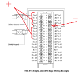
I finally looked at the pin out of the module and based on the pin out, I was able to successfully calibrate the module. Please see attached picture. apply your DC- to pin 9 and DC+ to pins 0 to 3 and 4 to 7 9 and 10 are common and this was the link in the puzzle I was missing. Forget remote terminal blocks or anything else; go directly to the pins on the module. An accurate signal generator or calibrator is recommended. Thanks all again.

1756-IF8.png
 
1756-IF8 : Channel Fault

Dear Sir,

My Analog Input module shows no Data, always channel fault, either under or Over range. But I applied 8mA. I configured Single ended current method. Anybody can help me on this pls.

Sorry, I will create new thread, I ask as you are online at this moment.

Thank you
Regards
Nagula
 

Similar Topics

Good Morning , I have a RTD , that I would like to wire into a 1756-IF8 Analog Input Card. Would you all a simple wiring diagram , of what...
Replies
4
Views
1,205
Hello! I am trying to wrap my head around how to wire a 4-20mA sensor to my AB 1756 ControlLogix IF8 Analog Input card. Could someone educate me...
Replies
3
Views
3,775
Hello, I have a flow meter that has been in service for a few years now. I have recently noticed that my registration on the mag meter does not...
Replies
0
Views
1,125
Hi all, iam facing problem in allenbradely analogue input module 1756-IF8, i.e one of the channel continuously fluctuating (CH NO-4). Iam not able...
Replies
5
Views
2,202
I am looking for information on the proper calibration of an 1756-IF8 analog input card, preferably the wiring of the voltage source. Rockwell...
Replies
10
Views
8,053
Back
Top Bottom