Weird PID control output bias%

jrowe4

Member
Join Date
Jul 2012
Location
palos park
Posts
16
Hello All! I have a PLC5 which is controlling a cocurrent drying process through a rotary kiln. I believe the control stategy of using an outlet to inlet air temperature ratio to control finished product temperature is a little strange. I would like to first try to explain the operation of the control strategy, then ask my question. Thanks before hand for taking the time out to read and offer any adivce!

We have two seperate PD PID loops which control the inlet air and outlet air. The only interaction between the two loops is a comparison of their CV which adjusts a gas valve.

Loop 1 Outlet Air - PV: Outlet air, SP: operator command, CV:Holds in an integer register for comparison

Loop 2 Inlet Air - PV: Inlet air, SP: operator command, CV:Holds in an integer register for comparison

-If the CV of the outlet air loop is <= the inlet air loop CV (meaning that the inlet air pv is farther away from its sp than the outlet air is) we begin to open the valve.

-Secondly, if the CV of the outlet air loop is > the inlet air loop CV (meaning that the inlet air pv is closer to its sp than the outlet air is) then close the valve.

The problem is as follows. Due to the control strategy (and possibly mechanical/chemical process problems) the air out PID does not reach SP ( error is always >= 100 refer to condition 1) so we begin to open the gas valve. However, the inlet air error reduces so fast( inlet air temp rises fast <= 30 secs; refer to condition 2) that we then need to close the gas valve. Once the inlet air error becomes large again (inlet air temp drops fast <= 30 secs) we start to open the valve. Bassicly this is a vicious cycle of on off control where the outlet air very very slowly tries to get to SP and the inlet air constantly is throttled. The material temperature is usually far from its SP (about 10 deg c) and the PV inches very slowly towards SP (Not sure if we even ever get to SP)

I took a look at the PID configs for the loops and noticed something very strange in the inlet temperature control PID which I just cant wrap my head around. There is an output bias % value of -425.0277. What in the world does this mean? Does it mean that we apply -425.0277% to the output term? I tried removing the bias but then the inlet loop PV started going well beyond its SP as oppsed to before where as soon as it got to SP the valve would close. I didn't want the process PV to hit the hi hi limit so I put the bias back in.

So my question is this. Why would such a negative bias be included in the loop? How is the bias affecting the process? I've asked a couple people here and they do not seem to know the answer. There was a lot of legacy knowledge lost from the plant and I'm fresh out of college so I am lacking in the process control knowledge area :oops:. I attached the program file as well as some graphs to better explain what is going on. If anyone can offer any words of wisdom I would highly appreciate it. Thank you so much for taking the time out to hear me ramble on this!
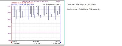
Graph of CVs.jpg
 

Attachments

  • process report.pdf
    71.2 KB · Views: 70
  • inlet loop PID config.pdf
    74.5 KB · Views: 94
Last edited:
First of all I don't think you are correctly interpretting the intent of the output comparison. This structure selects the lower of two PID controller outputs and uses that to control a single device. So it isn't trying to control the ratio of the temperatures. It is using the lower of two control efforts. Generally this is done because the process can live with the PV being a little low on one of the two but cannot live with the PV being too high on either.

I'm not familiar enough with AB PID instructions to know how it would react to a bias like that. From what I can tell it should limit at -100. You would be able to tell if you changed the bias to -101 and the output didn't change. At this point if you want to get that amount of bias out of there you will need to wait until the process is stopped or you will need to back it off slowly enough for the controller integral term to compensate for the change. The reason the temperature took off on you when you changed the bias was that the inlet controller output jumped up to 100%, egal to the outlet controller output. 100% was now the lowest available value so that was the output selected.

Again, I see no good that can come from a negative bias like that. The only thing that even remotely comes to mind is it will tend to cause the CV to ramp from zero if the instruction is enabled with a very large error on the cold side. But a large negative bias would be a pretty silly way of doing that.

Keith
 
Thanks for providing a seemily detailed description of your problem. It does raise some questions.

1) Has this control setup ever performed satisfactorily? This is where you need to seek history from some of the more experienced/tenured operators/technicians; people move around - find out where the past players are and speak with them. Seek out older documantation.

2) If it ever did work well then something must have changed. It could be equipment substitution/modification, instrument calibration, different process operating point, different product, changed program/tuning/parameterization.

3) The output bias setting is strange. Is something else in the program writing to this? (I don't think the AB PID initializes this on its own).

4) As written, the 2 PIDs with selection logic operates as a poor man's override control. I can't see this working well because the non-selected PID will windup (unless you don't use integral action, in which case you'll need that bias term).

5) I was just looking at 'Controlling Multivariable Processes' by Shinskey. In it he describes a cocurrent kiln control scheme. It uses an outlet temperature PID to cascade a setpoint to an inlet temperature PID which controls the heat input; the outlet temperature setpoint is biased in proportion to the actual inlet temperature (he provides some rationale for this). His books are out of print but used ones do show up on Amazon, etc.

Congratulations on your recent graduation and good luck with this problem. Keep us posted.
 
Thanks for the advice. I'm going to try to limit the bias to -101 and see if there is any difference. The PLC5 PD help text says that the output bias % is from -100 to 100. I'm still hung up on how that actually affects the output (In fact im still lost on feedforward for Interger PID blocks!). The current bias might of been put in as a "its 2am and I need this thing fixed" solution. I'm going to look into the relationship between the reset and bias, as well as check out that book. I'll post back later as there is another very unstable oscilating process that I am going to throw into manual and watch what the process variable does with no control. Thanks for all the help!
 
I suspect this will get jumped on as not exactly correct but the basic idea is here.

The basic independent PID implementation looks something like this:
Output = Err*Kp + SUM(Err * 1/Treset * tscan) + (Err - Err-1)*Tdiff / tscan) + OutputBias

After that you go through limiting:
If (Output > MaxOutput) Then
Output = MaxOutput
ElseIf (Output < MinOutput) Then
Output = MinOutput
End_If

In addition to this there is additional integral sum limiting so that the integral sum won't increase if at the max limit or decrease if at the min limit. There are also other functions performed that aren't really germaine to this discussion.

From what I can tell the output bias value is a free-standing value. By that I mean the value you enter is used directly. Another way it could be done is that when a change to the output bias is detected the difference between the last value and the new value is added to the integral sum.
So if you start the PID execution with the integral sum at zero and a large negative bias you will get no output until the integral sum reaches the negative bias value. After that the output will be allowed to increase.

I think you might be right with the 2AM fix thing. It looks like a value was just tossed in that would force the controller output to zero and basically let it re-establish a new level.

Keith
 
maybe this will shed a little light on the subject ...

this is just an effort to answer a couple of the nuts-and-bolts questions brought up by this thread ...

first of all:

How is the [negative 425%] bias affecting the process?

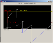
the graph below shows a PID instruction which is trying to control a "dummy" input signal (PV) that we are MANUALLY entering into the system ... this gives us an excellent method of putting the PID through its paces – for demonstration purposes ...

as the chart begins, the Setpoint (SP or "target" shown in yellow) has been dialed in at 75% ... we'll maintain that same SP all the way through the test ...

as the chart begins, the Process Variable (PV or "input" shown in red) has been manually entered as 75% ... (remember that this is a "dummy" value and it won't change unless WE manually change it) ...

since the PV is currently equal to the SP, then the Error (deviation from the target) is ZERO ...

in this steady state "demo" condition, the CV (Control Variable or "output" shown in white) is currently 0% ...

(1) at point A we've suddenly forced the PV to a new value of 25% ... the PID reacts by instantly stepping the CV up to 50% ...

this instantaneous change is due to the PID's Proportional action – which we will maintain at a setting of 1.00 throughout this entire test ... specifically, since the SP is 75%; and the PV is now 25%; the Error is now 50% ... the 1.00 setting for the Proportional action results in a one-to-one relationship – and so the PID now cranks out a CV of 50% ...

then the Integral action takes over ...

(2) our setting for the Integral action is 0.01 - and that same setting will be maintained throughout the entire test ...

note that we are purposefully using a very slow Integral action – so that we can watch its response on the graph ...

the Integral action ramps the CV from point A up to a value of about 85% at point B ...

(3) at point B we've suddenly forced the Bias Output to a value of (negative) -75% ... this has the effect of taking whatever CV value the PID is currently producing and SUBTRACTING 75% FROM IT ...

therefore ...

the PID instantly changes the CV from 85% at point B down to 10% at point C ... and then the Integral action continues to ramp the CV upward ...

(4) at point D we've suddenly forced the Bias Output to a value of (negative) -125% ... this has the effect of taking whatever CV value the PID is currently producing (about 32%) and subtracting ANOTHER 50% from it ... specifically, the old Bias setting of (negative) -75% and the new Bias setting of (negative) -125% gives us ANOTHER 50% of reduction from the CV ... which works out to be (negative) -75% ...

so ...

the CV instantly changes from 31% at point D to 0% at point E ...

and this is what makes this sort of thing "tricky" ... the PID that we're using cannot give an EXTERNAL output of anything less than ZERO ... but INTERNALLY the PID's calculation regards the CV as being about (negative) -19% ...

it's important to notice that the PID's "INTERNAL" math calculations will now regard the new CV to be about (negative) -19% ... that's "off the charts" and so the graph can't show it – which means that it's very hard for us to visualize the PID's operation unless we do some sort of "lab type" demonstration like the one we're doing here ...

anyway ...

as far as the PID is concerned, it now considers the CV to be all the way down in the basement at point X ... but the Integral action (bless its little heart) is still ramping the CV upward ...

so ...

from point E to point F we humans don't see the CV rising – because it's still "off the charts" and below ZERO ... but whether we can see it or not, the Integral action is still INTERNALLY ramping the CV upwards ...

at point F the Integral action has now ramped the CV up high enough to get back onto the chart ... and it continues upward to point G ...

(5) at point G we've suddenly forced the Bias Output to a value of (negative) -200% ... this has the effect of taking whatever CV value the PID is currently producing (about 14% and subtracting ANOTHER 75% from it ... specifically, the old Bias setting of (negative) -75% and the new Bias setting of (negative) -200% gives us ANOTHER 75% of reduction from the CV ...

so ...

the CV instantly changes from 14% at point G to 0% at point H ...

and we're back to the "tricky" part again ... the PID that we're using cannot give an EXTERNAL output of anything less than ZERO ... but INTERNALLY the PID's calculation regards the CV as being about (negative) -61% ...

since this is "off the charts" the graph can't show it ... as far as the PID is concerned, it now considers the CV to be all the way down at point Y ... but the Integral action keeps right on ramping the CV upward ...

and so again, from point H to point I we don't see the CV rising – because it's still "off the charts" and below ZERO ... but even though we can't see it, the Integral action is still INTERNALLY ramping the CV upwards ...

at point I the Integral action has now ramped the CV up high enough to get back onto the chart ... and it continues upward from there ...

so – are we having fun yet? ...

and now back to the first question ...

How is the [negative 425%] bias affecting the process?

I think you can probably see that it's throwing a king-sized monkey-wrench into the works ... specifically, the PID has to work itself to death just to get ANY amount of output at the CV ... that CAN'T be good for the system ...

continued in the next post ...

.

BIAS_PID_B.PNG
 
now for the next question:

Why would such a negative bias be included in the loop?

I can only guess – but I've seen this happen many times before – and I'll bet more than pocket change that the following is what happened ...

suppose that the PID is placed in the SW Manual Mode (SW for Software) ... suppose that the PID's Integral Gain setting has been entered as ZERO ... this ZERO setting usually happens during commissioning or tuning – to temporarily run the PID as a "Proportional Only" controller ...

here's the secret handshake:

in this condition, the PID will use the Output Bias location as a sort of "scratchpad" to handle certain of its mathematical operations ... oops! ... depending on what value you set for the Manual output – the "Output Bias" location can go either positive – or negative ...

and here's the scary part ...

once you've dialed back in some Integral action, the PID will quit using the "scratchpad" – BUT – it does NOT automatically clear the "Output Bias" value back to ZERO ... (gotcha!) ...

so ... I'm betting that once upon a time - someone was working/tuning/experimenting/tinkering with the PID with the Integral Gain setting temporarily dialed in at ZERO – and that the PID was being operated in the SW Manual mode – and that's what put that huge weird negative number in that box ...

party on ...
 
Last edited:
My PLC-5 online help says the Ouput Bias value is limited to +/-100%. Ron, you were obviously changing the bias to something more that 100%. Do they mean to say that you can't CHANGE the bias by more than +/-100%?

Keith
 
well, yes, based on the book I personally was under the impression that the values

-100 to +100

would have been the limits ...

but ...

when I cranked in those "beyond the limits" values mentioned in my post, the PID reacted as shown on the graph ...

specifically, the software allowed me to type in the "beyond the limits" values – and more importantly, the CV did NOT begin immediately ramping up from point E and from point H ...

more specifically, when I extended those lines down "off the chart" it looks obvious to me that the PID is working the way I described ... I can't imagine any other way to explain the results that I got ...

if you come up with another explanation, I'd love to hear it ...

going further ... I've helped debug several cases where the Output Bias setting had been "stuck" like this – but never with a value as outlandish as the one reported in this thread ...

and incidentally, the "Output Bias %" setting in this type of PID is often referred to as "Feed Forward" in other formats ...
 
Last edited:
well, yes, based on the book I personally was under the impression that the values
-100 to +100

would have been the limits ...
but ...
when I cranked in those "beyond the limits" values mentioned in my post, the PID reacted as shown on the graph ...
This is another example of book knowledge getting trashed by hands-on practical training.
 
All thank you so much for the help. Ron from what you are saying is that we can put values in well beyond the + - 100 (I hope this is what you meant!) This inner loop pid has to have a very large amount of positive error (pv is the far below sp) before control action is taken. Lets say the PID output as at 100%, that means that the CV had to travel ~500% just to get up to that 100%. I really don't feel comfortable with this! I do notice we actually switch to swm when a Hi temp is read in the inlet. This might be where that bias came from. I need to investigate this a bit more as I am trying to still learn about software manual mode vs station manual. I believe we use the tieback when working with manual control from a HMI and for bump less transfer (however for all our programs we only write to the tieback bit when the operator presses the manual button on the HMI. The CV output on screen jumps instantly when manual is selected!) S/M and A/M is probably for another discussion as I will search the forums before hand to learn as much as I can.

At this point, I believe there are a couple different options........
1. Throw inlet loop into manual and hold the temp steady until the outlet air pv is close to sp. At this point in manual I would remove the bias term, tune the pid blocks and make the switch back to auto.
2. Wait till process is down, remove the bias. On a process start up day tune the pid loops.
3. Maybe implement a new control strategy that cascades the inlet air as a slave to the master material temperature using cascade control as stated in the plc5 programming manual (this makes more sense in my head then the current control strategy) .

I have another process with horrible oscillations that I would like to do some manual control testing on before getting back to this process. When I found out more, I will post the results. Again thanks all for the help, this is a great learning experience!
 
Last edited:
So far the advice has been good.

The bias shouldn't ever be negative.
If the PIDs are tuned right one shouldn't need a bias unless the response needs to be faster.
If you want to use the bias as a feed forward to get faster response then the SP needs be ramped and not stepped.
The bias should be calculated like this
bias% = (SP-AmbientTemperature)*Kc
where Kc is the controller gain in %Output/DegreeError
Remember that SP should be ramped.
 

Similar Topics

I have created a project in TIA Portal v16 Upd6 with S7-1200 (6ES7214-1AG40-0XB0) and WinCC Unified (PC station). The communication between the...
Replies
4
Views
147
I currently have a weird issue involving Ethernet IP communication between a ABB CI873 (EthernetIP Module) and a 1756-L83ES. The Layout is as...
Replies
8
Views
760
Good morning. I'm doing a rehab and I need to recycle some part of the old code that won't change and that I need. This is a calculation that...
Replies
22
Views
1,371
I'm trying to figure out a weird behavior I'm seeing in my CCW program. It's for controlling a gas polarizer (for medical imaging). I'm using an...
Replies
6
Views
464
I'm trying to figure out some weird behavior I'm seeing in one of my programs. This should be fairly straightforward - except that it's not...
Replies
11
Views
954
Back
Top Bottom