Allen-Bradley Analog Input Module

flashman

Member
Join Date
Mar 2004
Posts
8
Hi,
I have an application calling for use of AI pressure transmitter inputs, (4-20ma) signal, to monitor pressure and then convert that current value to AO, current output, to control motor speed operation to a VSD.
Also, I need to send an alarm to a panelview if pressure is too high, and shut off the motor.
I'm not sure how to "collect" the current signal in the ladder logic program, then convert it and compare it to a preset limit for alarm situations. This alarm is then sent to a panelview 300.
 
Once the input module is properly set up, and that may be a subject of a whole other thread, the current signal is translated by the input module into a number appearing at a word address. (Individual contact inputs have appeared at individual bits of a word. The translated current will appear as a number occupying the whole word.)

How do you use this? There are commands which can move this number from one place to another, compare it with other numbers (checking for high pressure?), use math operations on it (perhaps to manipulate it to a related number to sen to an analog output module for the speed control).

You are in for a very interesting learning experience. Read the manuals carefully. Play around with a mock system. When you run into problems, come back here with what you have learned and we'll send you off for new adventures.
 
A bit more detail

I hope you don't feel that Bernie's reply was too vague, but your question was also vague, and so it would have been hard to answer your question more thoroughly.

You refer to an "Allen-Bradley Analog Input Module", but you don't give us a clue as to what family of processor (let alone input module) you will/may be working with.

You're challenge consists of four parts:

1) Get the Analog signal into the PLC
2) Convert the signal into something useful ("Engineering Units")
3) Compare the useful number to other numbers to set "Alarm Bits"
4) Get the "Alarm Bits" to the Panelview in a format that it can use to work with its standard alarming feature.

To give you an idea of what you may be up against (and why it's so hard to answer you fully), let's look at your options for Part 1 - Get the Analog signal into the PLC.

You have this Pressure Transmitter, with wires that have a 4-20 mA signal on them.

If you have a PLC-5 family of processors (perhaps with a 1771-IFE input module), then you will create a BTW/BTR pair of instructions, and the signal will come into the PLC as a number between 0 and 4095 (unless you configure it to be something else)

If you have a SLC family (perhaps with a 1746-NI4), then the signal will be in your I/O image table as a number between 3277 and 16383

If you are using a ControlLogix family (with a 1756-IF8 module), then you calibrate the module, and the signal will come in however you want it to.

I forget how MicroLogix handles Analog Inputs. Probably similar to the SLC.

If you decide on Flex I/O, then your method of getting the signal to the PLC is going to depend on the capabilities of the PLC and communication protocol used (Remote I/O; DeviceNet; etc.)

And so on. You get the idea. The key is to do what Bernie said - Read The Manual.
 
This will get you started. Note that A-B inputs for different models have different data structures and ranges, and some can be scaled to different ranges in the setup, and different PLCs have different commands. More info will get you a better answer.

For any unit conversion on any PLC you can use four function math with the following, which
asumes integer math:

DataOffset = Data in input register at 4 mA (or zero analog signal of whatever range
- for example 0 VDC on a 0-10 VDC transmitter)

DataSPan = Data at 20 mA - Data @ 4 mA

FACTOR = arbitrary factor (multiple of 10) needed to get proper resolution and accuracy

EU = Engineering Units x FACTOR

EUOffset = Engineering Units @ 4 mA x FACTOR

EUSpan = (Engineering Units @ 20 mA - Engineering
Units @ 4 mA) x FACTOR

DATA = Actual data reading in input register

EU = ((EUSpan x (DATA - DataOffset))/DataSpan) + EUOffset

ProcessValue = EU / FACTOR

For Example, 0-60 psig from 4-20 mA with resolution of 0.1 psig:

FACTOR = 10
Data @ 4 mA = 6240
Data @ 20 mA = 31208
DataOffset = 6240
DataSpan = 31208 - 6240 = 24968
EUOffset = 0 x 10 = 0
EUSpan = (60 - 0) x 10 = 600

DATA = 18975

EU = ((600 x (18975 - 6240)) / 24968) + 0 = 306

Process Value = 306 / 10 = 30.6 psig

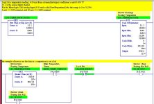
Here is an example from a MicroLogix 1200

1200_ai.jpg
 
Micrologix Analog i/o

The 1769 modules for the micrologix and compactlogix are fully configurable from Logix500 as long as you have a new enough version that the module appears in the i/o configuration dialog, module list. They are still fully configurable if not but you have to do it by sending a configuration file in run time.
 
micrologix 1200

Thanks for the "input"
The system calls for a micrologix 1200 with an IF2OF2 Analog input module, also an IF4 input module and a thermocouple mod. TC4.
So, it looks like I have to convert raw signal to an integer (N)value or register value and then compare with a GEQ,LEQ function?
Have to determine register length 0-32000 bits?
Have to get program language manual from AB website. The only manual that came with the system was for the editing of the software and loading.
 
1762 analog scaling

The 1762 analog units for the micrologix 1200 use either "scaled for PID" or "raw/proportional". For 4-20 mA the integer range is :

4 mA = 6241
20 mA = 31206

for "raw/proportional"

and

4 mA = 0
20 mA = 16383

for "scaled for PID"

If you want to convert to engineering units then use the scale with parameters instruction. SCP
 
Analog Input Module Question

Thankyou for your response! I have one more question. where did you find this information. I'm not sure I'm reading the right manual,
the one I have is the 1762-IF4 and 1762-IF2OF2 reference manuals. However there is no programming info. Only wiring diagrams and addressing info.?
Thanks again!
 
I found this thread doing a search and its been helpful, but I'm still stumped.
I was given a pressure transducer with a range from 11" to -10 (and no instructions). This is on a unit with a SLC 5/04. The analog card is a 1746NI4 (and no manual either haha). This is a replacement transducer and not the same brand as the original. I checked with a friend in the office and they said that at 0"WC the feedback signal should be 11.62mA, but he's not a programmer. (now I haven't been able to test 0", but with it just sitting on some angle I was getting readings of 11.32-11.40mA. So it's zero point is pretty close).
Anyways.. there are no manuals for the device or the card. Plus I have spaghetti logic to boot. I think it might be best to start fresh.
Could anyone point me in the right direction for setting this up? Currently I'm seeing a scp with a scl (right below it) in the same rung. I don't understand the scl command (rate & offset). I'm guessing this is key to getting the processor to actually see the right pressure. The logic also indicates that they want to average the reading over a series of 6 readings (which was also screwed up). Once I fixed the overflow issues the pid pv actually worked (though it is off by about 3.5" haha).
(they'd take 6 readings, add them together and then divide by 6...unfortunately after the 4th reading the number would exceed the 32767 value and stay at 32767).I split the groupings into 2 groups of 3 adds, stored each 1/2 then added them together and divided by 2. It now works. Currently I have the unit actively controlling right around -4.00"WC, but if you look at the logic it looks like the pv is -0.50"WC. horseshoes anyone? :)
I'd like to do this right and get a solid understanding of setting up analog devices/pids. It looks fascinating and fun.


Thanks,
Russ
 
Well, if the NI4 is like the NI8, and all you want is to get the data to read -10 to +11, then you would have an SCP, with input being from the NI4, and an input min of 3500, input max of 20500; scaled min of -10, scaled max of +11. This would be to view the data on some type of operator interface (what type of interface are you using? Is the range selectable for the tag?)

If you want to use the data in a PID, Use another SCP and it should be scaled with scaled min = 0, scaled max = 16386, with the output being an integer. This integer would be your PV.

I hope this is at least partially correct, I am sort of a newbie at this as well.
 
Help on 1769-IF4 with Logix 5000

Sorry guys, I am having another senior moment here. Found this thread but it don't quite answer my question. Yes, I have already read the manual. Why can't they write manual like they used to for PLC5?!

Setup: Compactlogic 1769-L32 processor, IF4 analog input (4-20ma)

Question: What scaling is used for IF4? The manual mentioned Twos-complenmentry, so it's 0-32767?? What's the difference between raw, engineering unit, pid, and precent range (0-100 right?)

Thanks much
 

Similar Topics

Hey Folks. I know its the same old struggle, but I need to get Analog Inputs into an AB system without any Analog Input Cards. Initially I...
Replies
15
Views
5,491
Hello to all. I am new to PLC’s as well as this forum so if I make any mistakes please forgive me. I am having an issue using the 2080 OF2...
Replies
9
Views
2,797
Hi, I'm curious if anyone has made a master sheet or cheat sheet for all allen bradley card's analog inputs/outputs? As much fun as it is to...
Replies
2
Views
1,581
This hasn't become my problem yet, but it may soon... Ancient PLC-3 (yeah, I know) has been humming along for decades. It now has some analog...
Replies
5
Views
2,457
Hello all. I have been working with an SLC 5/04 system, which houses various Digital and Analog INs and OUTs, up to Slot 29. I am currently...
Replies
3
Views
2,517
Back
Top Bottom