yawin
Member

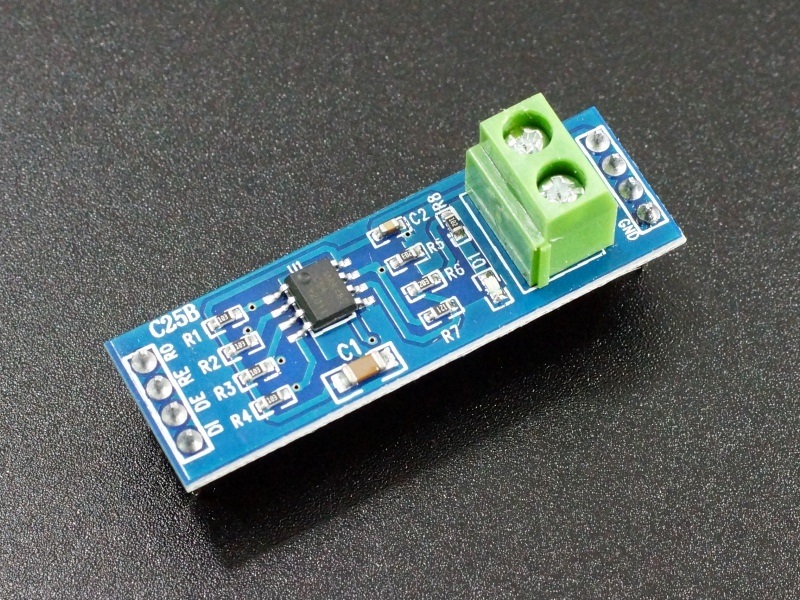
I'm trying to write a data in Arduino using MODWR function block .I used the code I got from online for both PLC and Arduino. I made the wiring between the MAX485 by referring online which I think may be I did some thing incorrect. But I think the PLC is communicating properly (COM 2 led is blinking) and Arduino code is printing '0' in serial monitor despite I'm sending data as I mentioned in Images I attached(---->Images for the connection program in plc<---link). The connection is as following
PLC to MAX 485:
+TO A
- TO B
SG TO GND
VCC NOT CONNECTED
MAX 485 TO Arduino:
DI TO RX
RO TO TX
DE,RE TO GND(Arduino GND)
PROBLEM: I'm not getting the value that I give to Arduino. pls help me.
Arduino code:-
//Serial Port (0 = TX: 1 - RX: 0)
int8_t state = 0; //Status variable for the Modbus input buffer
unsigned long tempus; //Variable to store the current time
uint16_t au16data[2]; //The table of records to be shared by Modbus
// initialize the library by associating any needed LCD interface pin
// with the arduino pin number it is connected to
const int rs = 12, en = 11, d4 = 5, d5 = 4, d6 = 3, d7 = 2;
LiquidCrystal lcd(rs, en, d4, d5, d6, d7);
//----------------------Program configuration-------------------------//
void setup() {
slave.begin(19200); //Open communication as a slave to 115200 baud
tempus = millis() + 100; //Save the current time + 100ms
digitalWrite(13, HIGH ); //Turn on the led of pin 13 (the one on the board)
lcd.setCursor(0, 1);
lcd.print("ValModbus=");
}
void loop() {
//Check the input buffer
state = slave.poll( au16data, 2 ); //Parameters: Table of records for the exchange of information
Serial.print(au16data[0]);
if (state > 4) { //If it is greater than 4 = the order was correct
tempus = millis() + 50; //Current time + 50ms
digitalWrite(13, HIGH);//Turn on the led (on the board)
}
if (millis() > tempus) digitalWrite(13, LOW );//Turn off the led 50ms after (on the board)
lcd.setCursor(10, 1);
lcd.print(au16data[0]);
lcd.print(" ");
}
PLC to MAX 485:
+TO A
- TO B
SG TO GND
VCC NOT CONNECTED
MAX 485 TO Arduino:
DI TO RX
RO TO TX
DE,RE TO GND(Arduino GND)
PROBLEM: I'm not getting the value that I give to Arduino. pls help me.
Arduino code:-
include <LiquidCrystal.h>
include <ModbusRtu.h>//Dołaczam biblioteke MODBUS
define ID 1 // ID Slave (Slave number 1)
Modbus slave(ID, 0, 0); //Node ID. 0 for the master, 1-247 for slave//Serial Port (0 = TX: 1 - RX: 0)
int8_t state = 0; //Status variable for the Modbus input buffer
unsigned long tempus; //Variable to store the current time
uint16_t au16data[2]; //The table of records to be shared by Modbus
// initialize the library by associating any needed LCD interface pin
// with the arduino pin number it is connected to
const int rs = 12, en = 11, d4 = 5, d5 = 4, d6 = 3, d7 = 2;
LiquidCrystal lcd(rs, en, d4, d5, d6, d7);
//----------------------Program configuration-------------------------//
void setup() {
slave.begin(19200); //Open communication as a slave to 115200 baud
tempus = millis() + 100; //Save the current time + 100ms
digitalWrite(13, HIGH ); //Turn on the led of pin 13 (the one on the board)
lcd.setCursor(0, 1);
lcd.print("ValModbus=");
}
void loop() {
//Check the input buffer
state = slave.poll( au16data, 2 ); //Parameters: Table of records for the exchange of information
Serial.print(au16data[0]);
if (state > 4) { //If it is greater than 4 = the order was correct
tempus = millis() + 50; //Current time + 50ms
digitalWrite(13, HIGH);//Turn on the led (on the board)
}
if (millis() > tempus) digitalWrite(13, LOW );//Turn off the led 50ms after (on the board)
lcd.setCursor(10, 1);
lcd.print(au16data[0]);
lcd.print(" ");
}