Two hydraulic cylinders control

Nemanja01

Member
Join Date
Jan 2023
Location
Belgrade
Posts
2
Hello everyone,

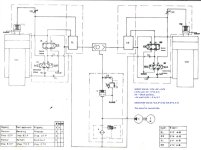
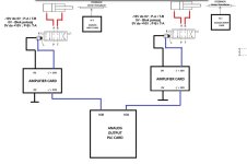
I'm reaching out for assistance regarding a project I'm currently working on. Specifically, it involves a hydraulic system with two cylinders, two servo valves, and two linear transducers for reading the position of the cylinders. I control the servo valves using an Analog Output Card with the PLC.

I have created two operating modes, manual and automatic. Essentially, the machine is functional, but I have one problem. The issue is that I cannot achieve equal movement of the two cylinders (there is always a slight deviation where one lags behind the other). By combining valve activation and setting a specific voltage in the range of -10V to +10V, I achieved fast movement of the press, slow movement - bending, and fast return of the press to its original position.
The machine is supposed to have three phases of movement. The first phase involves fast movement to the bending point. The second phase is the bending process itself. The third phase is the return of the press to its initial position. I determine the transitions between these phases based on mathematical calculations in the program, according to readings from the linear transducers of both cylinders (which is working well).

Can anyone help me solve the problem of uneven movement of hydraulic cylinders?
Note: I attempted to implement PI control where I obtained the error signal as the difference between readings from the left and right transducers. Based on the formula for PI control, I obtained the "error" which I added to one cylinder and subtracted from the other, but it did not solve the problem.

Attached you will find an image of the hydraulic schematic along with a brief description, the hardware configuration for controlling the servo valves, and an image illustrating the basic operation of the machine. I am also attaching the datasheet for the servo valves (I have amplifier cards made for controlling the servo valves).

Thank you in advance for your assistance.
 

Attachments

  • Hydraulic Diagram.JPG
    Hydraulic Diagram.JPG
    158.6 KB · Views: 33
  • System.jpg
    System.jpg
    40.3 KB · Views: 32
  • Servo Valves.jpg
    Servo Valves.jpg
    56.6 KB · Views: 33
  • HVM 09-100.pdf
    330.5 KB · Views: 9
Considering that you made amplifier cards for controlling the servo valves, all I can ask is have you incorporated Dither?
 
First I would change the Analog feedback transducer to a digital. Analog will never be as accurate as digital

Why are you using both a directional valve and a servo valve on each cylinder a good servo valve will give you both directional and flow control.

Using the 2 valves together they may be fighting each other.

Your control should be setup as master / slave configuration

You command the position of the master the slave always follows the master.
 
First I would change the Analog feedback transducer to a digital. Analog will never be as accurate as digital
Yes, use Balluff or Temposonic magnetostrictive transducers with an SSI interface
Why are you using both a directional valve and a servo valve on each cylinder a good servo valve will give you both directional and flow control.

Using the 2 valves together they may be fighting each other.
Yes.

Your control should be setup as master / slave configuration

You command the position of the master the slave always follows the master.
No, both actuators should follow a virtual axis.
Whenever you have control of the two actuators you should always gear both to a virtual axis.

This is how its done. This technique is easily extended to 4 corner presses.

If force control isn't necessary, then the pressure sensors or load cells are not required.
Presses usually push till a desired force or position is achieved.

A simple PI control will not work well.

There is no accumulator.
 
I also recommend using Balluff transducers, I used them to lift a 40 ton furnace with a cylinder and Balluff in each of the 4 corners and the precision is extraordinary.

I recommend that in the fast movement phases you continue to regulate the position and do not do so with the valves at full opening, because when the phase changes and it is time to regulate the position, it will already start with the cylinders equalized.

I recommend generating a position ramp for each phase, which will be the setpoint to regulate.
The regulation loop can be PI but as long as it is executed very quickly, every few tenths of a second.

Proportional solenoid valves better be of good quality, since there are simpler devices that are used to achieve some progressive control for cranes and construction machinery but are insufficient to achieve great precision.
Hello, thank you for reply... I understand that it's a better option to install digital transducers, but in my project, that's not currently feasible. This is an old press, which used to have NC control, and the idea is to switch to PLC. The press works well in terms of achieving positions and bending cycles, the only issue being a slight deviation in the cylinder movement.

System structure:
  • Siemens S7-1200 (1214C) PLC - 6ES7 214-1AG40-0XB0
  • Siemens S7-1200 Analog I/O device - 6ES7 234-4HE30-0XB0
  • Custom made current Amplifier board (I made an amplification module because the servo valve has a current range of +/- 300mA, and the output card of the PLC cannot deliver such a high current)
  • Linear analog transducer Novotechnik TLH-150
"I like your idea for generation a position ramp for each phase, which will be the setpoint to regulate.
Can you give me advice or an example of how I could do this most easily?
 
"I like your idea for generation a position ramp for each phase, which will be the setpoint to regulate.
Can you give me advice or an example of how I could do this most easily?
I call that a target generator. Some call it a trajectory profile or similar. This is the most difficult part of the motion controller and will not be easy to write in ladder. Structured text would be better and the S7-1200 may not have enough CPU power. The target generator should generate a new position every time increment or scan. This is what the actual position is compared too. The target position is the master position that both actuators should follow. The target generator should also generate a target velocity and acceleration too. The target velocity and acceleration are important because you multiply the target velocity by the velocity feed forward gain and the target acceleration by the acceleration feed forward gain and add the sum of these to the PID output. If done right the feed forwards gains should enable the actual position to track the target position closely. The PID only needs to correct for a little error. This can reduce the following error by a factor of 50 if done right.

Writing the target generator takes a little mathematics. I have software that makes it easy for me.
basically, you must solve for a few unknowns using a system of equations.
 
"I like your idea for generation a position ramp for each phase, which will be the setpoint to regulate.
Can you give me advice or an example of how I could do this most easily?

I would do it by executing a piece of code every few tenths of a second, for example every 0.5 sec, although it depends on how fast it moves, the faster the more frequently.
The time base better to be accurate.
You can have a phase table with two values per phase, the position increment or decrement every 0.5 sec and the final position at which the phase will be change when it is reached or exceeded.
Regulation is then executed next which will adjust the output value.
I would have no problem doing it in ladder with indexes to access the phase table.
 

Similar Topics

Hey guys, I've got a system that has 2 identical hydraulic cylinders, 8ft stroke, that operate using individual Proportional Control Valves. It's...
Replies
6
Views
3,793
Hello, I am raising and lowering a platform with four hydraulic cylinders with a height tolerance +/- 1mm. I was looking for the best possible...
Replies
2
Views
2,313
Hi All, I could do with some advice on a hydraulic control system. It is necessary for me to accurately position a vertical hydraulic ram with...
Replies
34
Views
1,916
Hi, I am about to start a project controlling a hydraulic ram using a Siemens S7-1200 controller. It will need to be quite steady control, by...
Replies
1
Views
759
Good Evening Everyone, I am attempting to monitor the level of hydraulic fluid in a tank. The tank is 50 gallons. For insurance purposes we need...
Replies
16
Views
4,170
Back
Top Bottom