You are using an out of date browser. It may not display this or other websites correctly.
You should upgrade or use an alternative browser.
You should upgrade or use an alternative browser.
Motor ?
- Thread starter T Gibbs
- Start date
geniusintraining
Lifetime Supporting Member + Moderator
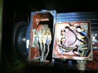
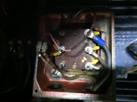
The peckerhead on the right just looks like a Y or Star connection with a thermal trip
What does the motor do?
What does the motor do?
OkiePC
Lifetime Supporting Member
Looks like a slip ring motor perhaps? I have never dealt with one. With that said, it looks to be wired between the two connection points already?
I would have fun with an ohmmeter and a notepad for sure, but first, I might call "S.M.A. Industrial Services Ltd" and pick their brains about it.
I would guess that you bolt your 3 phases to the connections on the right, but I would ohm them first and do my darndest to find a spec sheet on this motor. Then, before you throw the juice to it, if there remain any doubts, make sure there exists a spare
Last edited:
Looks like a slip ring motor perhaps? I have never dealt with one. With that said, it looks to be wired between the two connection points already?
I would have fun with an ohmmeter and a notepad for sure.
There is a cord coming from each of the peckerheads to go to the control cabinet. One went to the main contactor, the other went to a star-delta contactor, I think.
I've tried the ohmmeter. Set on meg-ohms, if I read between any terminal of one connection box and any terminal of the other connection box, it starts around 60 and climbs, continuously.
OkiePC
Lifetime Supporting Member
60megohms? So they are separate circuits, and I admit have no idea what to do with the one on the left...
The one on the right, verify you have balanced ohm readings between the studs and that they are not grounded.
I have seen some old systems where slip rings from one motor fed to another motor circuit, but they were small positioning motors built quite differently than what you have. What does this motor do?
alittlethiny
Member
It looks like a synchronous motor designed with dynamic braking.
Here is SMA's contact info, Phone, and E-mail address. Possibly SMA has wiring diagrams for this type of motor.first, I might call "S.M.A. Industrial Services Ltd" and pick their brains about it.
http://www.smaindustrial.co.uk/index.php
alittlethiny
Member
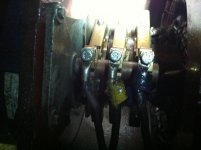
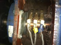
The one on the left is the power feed. The one on the right is the slip rings and you have to put external resistance across them to control the speed of the motor, from what I am understanding.
Take a look at this.
http://encyclopedia2.thefreedictionary.com/Dynamic+Braking+of+Electric+Drive
geniusintraining
Lifetime Supporting Member + Moderator
?? this is a nice drawing but the link does not work
http://www.google.com/imgres?imgurl...act=rc&uact=3&dur=1544&page=1&start=0&ndsp=41
I am sure they would have more info but their site is down
http://www.google.com/imgres?imgurl...act=rc&uact=3&dur=1544&page=1&start=0&ndsp=41
I am sure they would have more info but their site is down
It appears that the slip rings are 3-phase, 1 phase bare, 1 marked yellow, 1 marked blue. If so, this could be a wound-rotor motor, with a rotor having a coil fed by slip rings (instead of the usual induced-current rotor). The speed of a wound-rotor motor can be changed by changing the resistance between A-B, B-C and C-A of the wound rotor leads. Before electronic VFDs, wound rotor motors were used in cranes and other large loads.The one on the right is the slip rings and you have to put external resistance across them to control the speed of the motor, from what I am understanding.
Similar Topics
Hope you are doing well.
Currently, I am involed in a revamping project. It requires to stop a mixer at specific postion. For the detail, this...
- Replies
- 9
- Views
- 206
I'm looking for how others do it. I need to start a 1 phase motor. I have always used a regular 3 phase Motor Protected Circuit Breaker and looped...
- Replies
- 9
- Views
- 233
I've got this 3-phase 575V motor that we're controlling with a VFD (Variable Frequency Drive), which has been quite the learning curve in itself...
- Replies
- 10
- Views
- 314
Hello,
It is mandatory to use VFD IF i use IE5 electrical motor?
What happens If connect it directly as delta without VFD?
Please look at motor...
- Replies
- 1
- Views
- 166
Here's what happened,
Operator turned on the disconnect for an auger while it was still running to cut power. Auger DID in fact turn off, but the...
- Replies
- 8
- Views
- 372


