Understanding S7 code..

Matchu04

Lifetime Supporting Member
Join Date
Mar 2013
Location
Northampton
Posts
287
Evening all, I have got a program that I am trying to get my barnit around but wanted to clarify with someone with a lot more experience than my self.

I am having trouble trying to understand the FC316. From what I can gather MW100 is 2 bytes of bits that depending on the configuration determines the output word MW102. FC316 is a 40 word sequencer that evaluates that word at each step.

My questions...

Am I right in thinking that in FC316 the reference part is from LAR 1, as it is using the current db location??

Why at the start of FC316 is it SLW 4, I can see what that achieves??

When FC316 is first called DB100 is opened, how do I go about finding the correct sequence for each step as DB100 does not have 40 steps in it..

I appreciate that there is a lot here guys but I would be so grateful for the help..
 
Why at the start of FC316 is it SLW 4, I can see what that achieves??

I had a feeling I had asked this question before... and it was indeed the case. Since the program was converted from S5 to S7 the "convertor" loads the STW into a temp variable, before the LAR1 instruction and then reloads the STW after...
 
AR1 is used to indirectly address the input word masks and output word bit patterns. The input word masks start at DBW100 but because the step number is added to the offset before the SLW 4, the constant 50 is used. Similarly for the output words which start at DBW20 so the constant 10 is added to the step number. See my recode which codes the offset into the indirect instructions (is this any clearer?).

For indirect addressing AR1 contains the bit address so to access a byte offset use SLW 3 (multiply by 8), to access a word offset use SLW 4, to access a doubleword offset use SLW 5

The sequencer will step on after step no 7 all the way up to step 40 and then reset to step 0 because the input word masks are all zero.

Note that STON should be an inout parameter as it's status is checked before it has been evaluated. However, as your code uses M flags you are "getting away with it"

Code:
FUNCTION "SEQ1WW" : VOID
TITLE =
NAME : SEQ1WW
VERSION : 0.0


VAR_INPUT
  IW1 : WORD ;    // IW1 
  ENAB : BOOL ;    // ENAB
  RES : BOOL ;    // RES 
  LFLT : BOOL ;    // LFLT
END_VAR
VAR_OUTPUT
  OUT1 : WORD ;    // OUT1
END_VAR
VAR_IN_OUT
  STON : BOOL ;    // STON
END_VAR
VAR_TEMP
  conv_akku1 : DWORD ;    
  conv_stw : WORD ;    
END_VAR
BEGIN
NETWORK
TITLE = 40-STEP 16-BIT FILE SEQUENCER

      L     W#16#0; // INITIALLY ZERO OUTPUTS
      T     #OUT1; 
      T     DBW   12; 
//;
      AN    #RES; // CHECK IF RESET
      JC    M001; // JUMP PAST RESET IF NOT
      L     0; 
      T     DBW   10; 
//;
//;
M001: AN    #ENAB; // CHECK IF ENABLED
      BEC   ; // BLOCK END IF NOT ENABLED
//;
//;
      L     DBW   10; // GET PRESENT STEP NUMBER
      SLW   4; // word offset
      LAR1  ; 
      L     DBW [AR1,P#100.0]; // GET REQUIRED INPUTS "ON" WORD
      L     #IW1; // GET ACTUAL INPUTS
      T     DBW    6; 
      AW    ; // MASK OUT UNWANTED "ON'S"
      XOW   ; // DETERMINE MISSING "ON'S"
      T     DBW    2; // PUT RESULT IN DW1
//;
//;
      AN    #LFLT; // EXAMINE LATCH FAULT COMMAND
      JC    M002; // IF OFF,JUMP PAST LATCH
      L     DBW   16; 
      OW    ; 
      T     DBW   16; 
//;
M002: L     W#16#0; // GET ZERO BIT PATTERN
      L     DBW    2; 
      ==I   ; // COMPARE WITH DW1
      AN    #RES; 
      AN    #STON; 
      =     #STON; // SET ON "STEPON" IF EQUAL or if dbw2=zero
//;
//;
      AN    #STON; // EXAMINE FOR NO STEP-ON
      JC    M003; // JUMP PAST INCREMENTER
      L     DBW   10; 
      INC   1; // ADD 1 TO STEP NUMBER
      T     DBW   10; // TRANSFER TO STEP NUMBER
      L     40; // GET DECIMAL 40
      <I    ; // COMPARE STEP IS LESS THAN 40
      JC    M003; // IF SO,JUMP PAST ZERO STEP
      L     0; 
      T     DBW   10; // ZERO STEP NUMBER.
//;
//;
M003: L     DBW   10; // GET STEP NUMBER
      SLW   4; 
      LAR1  ; 
      L     DBW [AR1,P#20.0]; // GET OUTPUTS BIT PATTERN
      T     #OUT1; // TRANSFER TO OUTPUTS.
      T     DBW   12; // & TO DATA WORD 6.


END_FUNCTION
 
I think I have just had a small eurka moment with regards to indirect addressing, but need to polish it up ..

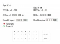
I was always under the impression when we talk about a pointer, especially regarding a specific byte, we are using the same struct as a the accumulators. This is very much not the case. I was struggling to see how SLW 3 actual moves a byte along. For example when you shift 255 left 3 places, not all the bits move along. So when we talk about a pointer, its a complete different structure.

Next then, regarding the bit I call the pointer, which is in fact the location of the data,

Code:
L     DBW [AR1,P#0.0];

In this example a "register indirect address" we point to area '''DBW" with the address of AR1, with an offset of 0.0 .

Then the finally piece of the puzzle...

AR1 is used to indirectly address the input word masks and output word bit patterns.

Hence the load after the SLW 4 is the adress pointer of the offset

Poiter 2.jpg
 
Last edited:
Note that STON should be an inout parameter as it's status is checked before it has been evaluated. However, as your code uses M flags you are "getting away with it"

Code:
      AN    #STON; 
      =     #STON;

I can see what you are saying regarding #STON in my FC316, could you expand a bit more this, for example you say since M flags are being used???

Is it do with the way the FC is called?
 
Regarding the SLW 3/4/5. I always use SLD 3/4/5 as the largest byte you can address using a word is DBW8191 - sometimes the DB can be larger than this.
 
Another thing I wanted to ask LD, when you post the code using;

Code:

can i put this straight in the editor?? I did try earlier but it wasnt happy
 
The posted code is in source code format. You create an STL source code container in the sources folder, open it, then paste in the source code and then compile it to generate the relevant block in the blocks folder.
 
The posted code is in source code format. You create an STL source code container in the sources folder, open it, then paste in the source code and then compile it to generate the relevant block in the blocks folder.

Arh sweet, always wondered what the source folder was all about...
 

Similar Topics

Good day, First time posting here. I am currently working on migrating an Allen Bradley Micrologix 1500 to Siemens S7 1200 and i came across...
Replies
4
Views
1,346
Could anybody please tell me what algorithm use following S7-SCL code. I understand it is a value as input then making output. But i want to know...
Replies
4
Views
2,583
call #v10A1 enable :="valveDB".v10A1.Enable DB24.Dbx0.0 Interlock := open_feedback := "mapped-do".D0_1.V10A1 DB104.DBx0.0 close_feedback :=...
Replies
3
Views
2,231
Would someone please explain the following bit of code from a step 5 program or, if possible, convert it to ladder so I can understand it? I don't...
Replies
2
Views
1,533
I have been doing programming of A/B plc's for about 8 years, now I have been kinda forced to take on a new job and they use Panasonic FP-e and...
Replies
13
Views
3,603
Back
Top Bottom