OT. Schematic questions

g.mccormick

Lifetime Supporting Member
Join Date
Jul 2012
Location
IN
Posts
961
Two questions.

1. For those of you that use the relay expansion boards such as:
https://www.automationdirect.com/ad...ions_Modules_(Complete_List)/ZL-RRL16HDF-24-1

How do you show on the schematics that the relays are all part of a device? Before I have just shown the relays as stand-alone coils with no real connection to them being part of a "board".


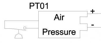
2. Next question is what do you typically use for a pressure, flow, temperature transmitter symbol? My symbols are just basically square boxes with some wire connections. Does anyone have a nicer representation of for instance MA output pressure transmitter?
 
put the device on a separate page, or put a box around each coil, the contacts can be on other page with references.

2. that is depending on your cad software.
have a look at www.qelectrotech.org for a free ECAD program. with lots of symbols.
 
In general, to show a mechanical connection among devices, I will use a dashed line or enclosing rectangle (with dashed linetype).

So if your relay coils are all on a sheet, put a big dashed rectangle around them. Sometimes it is useful to put the part number or a brief description at the edge of this rectangle or if it is extended across multiple sheets, a note explaining that.

I use JIC symbols and make my drawings old school 'merican style, and I have not found a good symbol I like for transmitters. So, I make a rectangle with attributes for terminal points and put a multi-line text object in the middle of it with a description.

+1, I do the same exact thing.
 
In general, to show a mechanical connection among devices, I will use a dashed line or enclosing rectangle (with dashed linetype).

So if your relay coils are all on a sheet, put a big dashed rectangle around them. Sometimes it is useful to put the part number or a brief description at the edge of this rectangle or if it is extended across multiple sheets, a note explaining that.

I use JIC symbols and make my drawings old school 'merican style, and I have not found a good symbol I like for transmitters. So, I make a rectangle with attributes for terminal points and put a multi-line text object in the middle of it with a description.

+1 From the maintenance side.
If I see something wrapped in dashed lines I expect that is either in a separate cabinet or a separate component. As long as there is some explanation, I'll find it.


Wubba.
 
Thanks for the input guys. I will do that for the relay cards. I've done something similar in the past for for sensor input "modules".

Now to find a better transmitter symbol than my box. I know I've seen something before with a diagonal line seperating the pressure to ma side. Similar to what I use for an ac to dc power supply.
 
What I do for a transducer is use a standard sensor/switch wired to want I use for a servo or analog output.
This is an example of a pressure transducer:

PT.jpg
 
We use EPLAN.

1: If a device has a mounted option, I would use the tag of the device, with perhaps a subordinate tag. So say PLC device A151 has a relay option installed, I would maybe call that -A151-K1.

2: See picture.

Transmitter.jpg
 
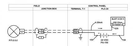
Schematics aren't the same as wiring diagrams. Schematics are intended to show the function of a circuit, for use in design and troubleshooting. Wring diagrams show point to point connections or construction.

I never liked the convention of showing all the PLC I/O on a single block for schematics. The same would apply to a relay card. If the circuit is complex it is difficult to show the related components clearly. I also separate discrete circuits from analog circuits. With the proper label you can easily identify the PLC I/O card and channel that the I/O or relay is associated with.

I've attached samples. Over the years I've had many contractors tell me that my drawings were the easiest to work with they had used.

ch11fg06.jpg loop diagram.jpg
 

Similar Topics

E
My most immediate concern is how to represent my PLC (inputs, outputs & logic) in my electrical schematic that I need to provide to my customer...
Replies
2
Views
11,321
Hello, fairly new to plcs I’m tasked with installing a PE to a micrologix1200, in the attached picture I/14 is the PE I’m installing it’s going to...
Replies
6
Views
946
This is my first IO-Link project. I am having trouble figuring out how to draw this in ACAD-E. How to show the system as well as the wiring to...
Replies
6
Views
1,756
There are so many different ways to tackle the first sheet of the schematics. I've seen some people with a cover sheet, followed by several...
Replies
13
Views
2,599
Which Style to you expect to see on a drawing? Which style to you prefer? Keep in mind this being used on very large projects Style 1 Style 2
Replies
21
Views
6,741
Back
Top Bottom