Multiple ControlLogix Controllers in the same Chassis

ebolbol

Member
Join Date
Apr 2011
Location
CA
Posts
175
I have just seen a program so complex and so plc memory intensive, that it takes 4 individual L73 controllers in the same chassis to share the processing, execute tasks, etc.

The first controller installed obviously becomes the primary controller that contains the controller tags. But how would you write logic and assign to a specific controller in the rack? Very interesting. Has anybody seen anything like this?
 
Sure. They are programmed individually just as if they were all in the chassis by themselves. Each CPU has their own program, and they might not even know about the other CPUs.

There is not a primary PLC. They are all standalone controllers.

OG
 
I've also seen this done when multiple OEMs needed to contribute to the same control system and share the same network.

Each one got their own CPU, shared inputs, owned outputs, and did Produced/Consumed Tags to communicate with one another.

In the old days we did it with L1 controllers and would split up motion control from continuous process control, as well.

Old days. Get off my lawn !

So Produced/Consumed must be the trick. When you open the project, the I/O tree looks like any other project, but there is a difference. Not all is what it seems. certain tasks and programs and routines are done by various controllers and not necessarily by the main controller. Huh...
 
I've not seen four CPU's in a chassis, but I have seen two. This was on a high speed can printing machine (think 35 cans per second), where one CPU did 99% of the work, and the other one had just one routine, written in ST, which ran as fast as possible and handled only the timing of the print rollers. The two processors communicated using produced/consumed tags, but the only communication going on was the fast PLC telling the main PLC "I'm ready to go", and the main PLC telling the fast PLC "start printing now".

Anyways, as the resident young whippersnapper, I better get off Ken's lawn ;)
 
When you open the project, the I/O tree looks like any other project, but there is a difference. Not all is what it seems. certain tasks and programs and routines are done by various controllers and not necessarily by the main controller. Huh...

It looks like any other controller. There is no "one project that rules them all". The project is not distributed, there is no inherent master controller. Your application programs might consider one controller to be the main/master, but there is nothing inherent that makes any CPU the main/master controller.

Each CPU has its own project, logic, tags, I/O modules. As Ken mentions though, input modules may be shared among multiple CPUs. Not output modules though. The only thing that might stand out is that if they are using Produce and Consume then the I/O configuration will also show the other controllers. But that would also happen if they were all in separate chassis.

Imagine the four CPUs in four separate chassis. This works exactly the same as if they were all remote.

OG
 
Last edited:
It looks like any other controller. There is no "one project that rules them all". The project is not distributed, there is no inherent master controller. Your application programs might consider one controller to be the main/master, but there is nothing inherent that makes any CPU the main/master controller.

Each CPU has its own project, logic, tags, I/O modules. As Ken mentions though, input modules may be shared among multiple CPUs. Not output modules though. The only thing that might stand out is that if they are using Produce and Consume then the I/O configuration will also show the other controllers. But that would also happen if they were all in separate chassis.

Imagine the four CPUs in four separate chassis. This works exactly the same as if they were all remote.

OG

Very very interesting indeed.... have to poke around to see if I can figure it out
 
Imagine the four CPUs in four separate chassis. This works exactly the same as if they were all remote.

OG

That, in a nutshell, describes the situation perfectly !!

I always make a point to my students that the "chassis" just contains a "backplane", which is a network component, allowing whatever modules that are plugged onto it to communicate with each other.

I also point out that every single module can be considered to a "processor", performing different processing functions. Input modules process real-world inputs into Input data tags, output module process Output data tags to real-world outputs, communication modules act as "bridges" from the chassis to other devices, so they are processing data that needs to be communicated, etc.

They all communicate with each other using the Producer/Consumer model of data exchange.

After more discussions about limitations in sharing I/O modules, I tell the students that the networked 3, 4 or 5 training rigs in the room (each with 2 controller modules), can be looked at as one "PLC" - I prefer the name DCS - Distributed Control System.

I have to stick to the course material, but if time allows I like to throw in additional exercises, e.g....

1. Use your potentiometer (analog in) to display on the panel meter (analog out) of the training rig to their right. This concentrates on configuring local and remote I/O, and usually initially gives errors because the chassis to the right still has the last exercise in the controller, which has control of the unsharable analog output module. It's a good exercise because the students see first-hand what the problems are, and how they become resolved automatically.

2. A "chat-room" - it's fun and it involves creating a bunch of produced and consumed string tags. There's no I/O or coding involved, just produce/consume tag data-exchange. Also they have to put everyone else's controllers into their I/O Configuration, nothing in the standard course material goes anywhere near that scenario.

In summary... Any module - Any where : it's just a collection of modules on a network.
 
The only thing that might stand out is that if they are using Produce and Consume then the I/O configuration will also show the other controllers.

Just to clarify that....

A controller can "Produce" tags, without the need to put any of the consumer-controllers into the I/O configuration. You just needs to specify the number of consumers when creating the Produced tag.

It is only necessary to put remote controllers into the I/O configuration when "Consuming" tags from them.
 
That, in a nutshell, describes the situation perfectly !!

I always make a point to my students that the "chassis" just contains a "backplane", which is a network component, allowing whatever modules that are plugged onto it to communicate with each other.

I also point out that every single module can be considered to a "processor", performing different processing functions. Input modules process real-world inputs into Input data tags, output module process Output data tags to real-world outputs, communication modules act as "bridges" from the chassis to other devices, so they are processing data that needs to be communicated, etc.

They all communicate with each other using the Producer/Consumer model of data exchange.

After more discussions about limitations in sharing I/O modules, I tell the students that the networked 3, 4 or 5 training rigs in the room (each with 2 controller modules), can be looked at as one "PLC" - I prefer the name DCS - Distributed Control System.

I have to stick to the course material, but if time allows I like to throw in additional exercises, e.g....

1. Use your potentiometer (analog in) to display on the panel meter (analog out) of the training rig to their right. This concentrates on configuring local and remote I/O, and usually initially gives errors because the chassis to the right still has the last exercise in the controller, which has control of the unsharable analog output module. It's a good exercise because the students see first-hand what the problems are, and how they become resolved automatically.

2. A "chat-room" - it's fun and it involves creating a bunch of produced and consumed string tags. There's no I/O or coding involved, just produce/consume tag data-exchange. Also they have to put everyone else's controllers into their I/O Configuration, nothing in the standard course material goes anywhere near that scenario.

In summary... Any module - Any where : it's just a collection of modules on a network.

daba,

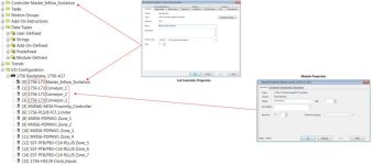
I sorta understand what you're saying, but still failing to see how tasks are executed among the four L73's. Only the primary has tag database and shows full controller properties as shown in pic, the rest.... when double clicked, just L73 basic module properties. I have collapsed the rest of the tree for confidentiality of the owner.

Untitled.jpg
 
Presumably, you have opened the program of the first controller in the chassis (Master_Inflow_Sortation). As far as it's program is concerned, it's a Controller and the other three are just I/O modules. So you will get a "Controller Properties" for itself, and "Module Properties" for the other three.

Remember, each of the four L73's has it's own PLC program!

What you are looking at there is NOT the program executed by ALL FOUR processors - you're looking at just the program executed by the processor in slot 0.

The other three L73's have their own program, and their own .ACD file. They will probably all look completely different to one another. If you open the program for the second one, you'll find that the second controller views the first as an I/O module, just like the first does the second.

Does that make any more sense?

ASF,

OK... that just clarified the hell out of everything for me. šŸ™ƒ Now I get it. Each one of the L73's have their respective projects independent of one another. Thank you so much.
 
Look at the I/O config and next to the "[0]" there is a little left facing arrow icon. That is how we know that you are looking at the application for controller in slot 0.

If you go online to slot #1 you will see the same little icon next to [1]. Again, they all operate independently with their own applications.

As ASF mentions, each controller has the other controllers in their I/O configuration for the purpose of messaging or Produce and Consume. But to the controller in Slot #0, then modules in slot #1 and so on, are treated just like I/O modules. That's why you can't drill any deeper to see the code. The code is in the other controller.

You have four completely independent CPUs that just happen to be located in the same physical chassis. Treat them as four independent systems.

OG

Operaghost,

It took me a while, sheeesh... šŸ™ƒ but I finally get it. It also makes complete sense. I have to see if I can fetch the other projects that contain the code for the other controllers. Thanks tons gents :geek:
 

Similar Topics

I am trying to add 9 DINT values with the CPT instruction in ControlLogix and I keep getting errors. I am just choosing each tag with an add...
Replies
13
Views
2,323
Hi folks, I'm new to this forum, learning my way around. Please bear with me. At my company, a contractor is wrapping up a project where multiple...
Replies
4
Views
2,045
For the first time today I tried to create a second motion group in a ControlLogix PLC, but the "New Motion Group" option is grayed out. Is it...
Replies
3
Views
3,491
ControlLogix 1756-L71 version 20.55. I want to poll this controller from two separate GE iFIX 5.5 SCADAs using the IGS 7.58 driver. Each SCADA...
Replies
1
Views
1,360
Hi, I branched a previos thread so this only deals with one subject. The Rockwell Power Monitor 500 presents several instances for its data...
Replies
6
Views
3,528
Back
Top Bottom