Another newbie question

John Morris

Lifetime Supporting Member
Join Date
Sep 2015
Location
San Antonio
Posts
689
Good Morning to all

FTV 8.0, RSL5K,

I have set up a Multi state indicator. Its just a light, but I need it to change colors with the state of the motor.

Blue = motor off
green= motor on
red= motor in overload.

I have each of the tags set in RSL5K.

I have read several post and I think I know what to do, but please confirm

Create DINT tag in the controller and label it PUMP_MOTOR_STATUS.

Take the three tags for each condition and assign them each to a box under the DINT.

Then point the multi state indicator to the dint and whichever box lights up that's the state of the indicator.

Do I have my head wrapped around any part of this correctly?

Thanks For the time and consideration
 
I think the way you are trying to do it, is to have a number represent each state of PUMP_MOTOR_STATUS for your HMI display.

So if in RSL5K; PUMP_MOTOR_ON then move a 1 into PUMP_MOTOR_STATUS.
If PUMP_MOTOR_OFF then mova a 2 into PUMP_MOTOR_STATUS.
If PUMP_MOTOR_OVERLOAD then move a 3 into PUMP_MOTOR_STATUS.

In FTVStudio have your multistate indicator pointing at {PLC}PUMP_MOTOR_STATUS with 3 states configured. When PUMP_MOTOR_STATUS = 1 (or 2 or 3) then that state will be displayed (blue, red etc).

There are of course different ways to achieve the same thing.
 
So, yes the multistate indicator is expecting a numeric state value.

You can either use the PLC logic to set the proper numeric value in your DINT, Or, if you already have 3 BOOL state bits, you can use the expression editor and a quick state table to accomplish the same thing in the HMI.

For example
Code:
If State1 AND NOT State2 AND NOT State3 Then 0
Else If NOT State1 AND State2 AND NOT State3 Then 1
Else If NOT State1 AND NOT State2 and State3 Then 2
... etc
 
Dravik

Writing code is like speaking A foreign language. But I need to learn. My logixs skill are still very new. I am better with ladder.

So I think you guys are telling me I can do this.

Controller tag PUMP_STATE

Paralleled to the output PUMP_STATE.1

Paralleled to the overload input PUMP_STATE.2

Made another line with XIC output, and XIC overload =PUMP_STATE.3 (off)

Pointed the HMI MSI at the PUMP_STATE controller tag......

I guess I need more clarification. Have I done this correctly or is there more to connect the PLC tags to the HMI MSI

I really do appreciate the time.

Thank you
 
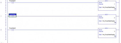
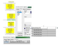
As Ocean pointed out, at its simplest it would look like the attached picture.

Look at each rung as saying -
If PumpStateX Then Set Hmi_PumpStateDisplay to Y

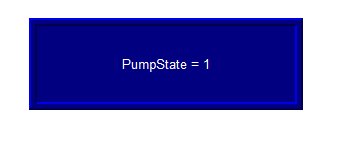
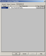
Then you would point your multistate indicator at Hmi_PumpStateDisplay, and config states with values 1,2,3 to display what they should.

Simple_PumpState.jpg multistate.png multistate_states.png multistate_connection.png
 
Last edited:
Now, you can make that logic more complex to suit your needs.

Maybe you need to indicate when the pump is reporting it is ON AND Overloaded, seperatly from OFF AND Overloaded.

Then you would add addition conditions to your logic and new states.

You can also put those 3 rungs into a single rung w/ branching.
 
Don't worry about the PLC code if that's confusing right now, Write it out in pseudocode like you did in your post. Then translate that to the PLC or HMI logic.
 
Well, i'm not 100% on what you were describing in the first post, but the dint PUMP_STATE can be connected to the multistate indicator sure.

But you need to manipulate the value of the DINT somehow to make the indicator change.

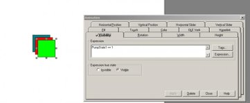
Now, if you are building your OWN multistate light using conditional visibility, Well then that's a different can of worms!
In that case, you would have 3 layers, each of which is a different color, and you would tell those layers to be either visible or invisible based on the state tags.

Edit:

Something like this?

light.jpg
 
Last edited:
Basically

the first three of the DINT are under the pump status

Wouldn't the dint change if the tag did which intern would change the state of the indicator.

all.jpg
 
If you use the first 3 bits of DINT then you have to change the Values on the Multistate Indicator. you can not use 0,1 and 2 for the value of the Multistate indicator.

The Binary values of the DINT will be 0-7 depending on the bits that are true.
if bit0 =0 and bit1=0 bit2=0 the DINT =0
if bit0 =1 and bit1=0 bit2=0 the DINT =1
if bit0 =0 and bit1=1 bit2=0 the DINT =2
if bit0 =1 and bit1=1 bit2=0 the DINT =3
if bit0 =0 and bit1=0 bit2=1 the DINT =4
if bit0 =1 and bit1=0 bit2=1 the DINT =5
if bit0 =0 and bit1=1 bit2=1 the DINT =6
if bit0 =1 and bit1=1 bit2=1 the DINT =7

Since you only have 3 states if status bit0 and status bit1 are both true then the multistate will show error because your DINT = 3 if your status bit2 is true you'll get an error because your DINT = 4.

You don't need the Status DINT to have the multistate show the correct status of your motor. Just use an expression instead of the tag. click on the expression and copy this below.

IF {[L30ER]WSH_PMP_ONE_OLVD} THEN 2 ELSE
IF {[L30ER]WSH_PMP_ONE_ON} THEN 1 ELSE 0

The expression evaluates from top to bottom so by putting the overload condition first it is given priority to show if true. So this expression is saying if I am not overloaded and I am not ON then I am OFF.
 
Best i've heard all day.

I actually understand why that won't work now.

I thought it was more like a placeholder, instead of just a hole.

course binary is a foreign language. which means writing expressions is out.

Dravik's suggestion is doable.

I'll try that.

Thank you cwal16

Thank you everyone for your valuable time.
 
Actually, I think setting bits of the DINT tag PUMP_STATE will work quite nicely. Just a bit different than proposed.
PUMP_STATE.0 set it to be ON when the pump is running.
PUMP_STATE.1 set it to be ON when the pump is overloaded.
Now PUMP_STATE behaves like this when viewed as an integer:
0 = Off (You get this for free, it is 0 if it's not running or overloaded)
1 = Running
2 = Overloaded
3 = Overload and running? I don't think you need to worry about this combination since the motor will stop when you have an overload. But if it worries you, just have state 3 say "Overload" too.
 
Last edited:
Looking at your logic picture it seems that
bit 0 = pump off
bit 1 = pump on
bit 2 = overload
IF
State 0 = off
State 1 = run
State 2 = overload
Then
change the value of State 0 =1
change the value of State 1 =2

and if your logic for an overload turns off the run output and turns on bit 0 then State 1 = 5

The Value shown in the Multistate Indicator only matches the state number because that is its default value when you create the indicator. You can change that value to meet your requirements.

It also looks like your descriptions are coming from the DINT since all bits are describe the same. If you click on the + sign by the DINT then you can describe each individual bit. I would suggest something like this.

Pump 1 On
HMI USE ONLY

If you are only using those bits to set your Multistate indicator this will indicate there purpose for being there. This will also let the next person looking at the program know there purpose.
 
cwal16

Thank you, that's sage advice.

I will change the Dint labels now.

Just as a follow up, she was powered up about an hour ago, and the logic worked. All of it. Had a few bugs with the stack light. But Two tags of scada input and she ran completely autonomous. I am a proud papa.

Off topic

One of my hobbies was rebuilding 350's. Over my lifetime, I have rebuilt close to fifty engines. Of those fifty, you know how many started on the first try.......7. know how many I had to rebuild before that, 43.

This was my first RSL5K program, and all my bugs were in the stack light sequencer.

Want to thank everyone on PLCS.net for putting up with my rookie ( and sometimes obviously stupid questions ) and helping me achieve what was otherwise a flawless start up.

Thank you ALL..............................
 

Similar Topics

Hi All, I'll looked through the forum and the vastness of google with little luck (which makes me believe what I'm going to ask is not possible)...
Replies
4
Views
3,638
How do you repeat a subroutine? I'm able to jump to the subroutine execute it then return. But basically I need to run the same subroutine twice...
Replies
11
Views
4,921
Hi Guys Interesting forum you have here. And some interesting comments to the Newbies. I promise, i'm not here to ask you to do my homework...
Replies
2
Views
4,530
Hi All, I've been using GE and Siemens for a long time and just switched to Allan-Bradley because of one of our customers requirements...
Replies
21
Views
4,577
Hello everyone? I’ve been lurking for some time…This is who I am. I’m 56 I’ve been in plant maintenance for the past 4 years as an electrician...
Replies
8
Views
3,079
Back
Top Bottom