Forces In Rslogix 5000

BIGE

Member
Join Date
Sep 2004
Location
Meridian,Mississippi
Posts
20
This is for troubleshooting pourposes. How do you force I/O's in RSL5000? I'm new to it and am not having any luck. I know I,m missing some small detail somewhere.

Eric
 
may the force be with you ...

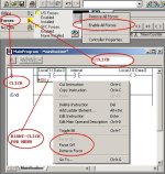
play around (SAFELY!) with these ideas and see if it starts making sense ... note that you cannot “force” internal tags ... only real-world inputs and outputs ... specifically, the “internal” tag in the figure can not be “forced” ...

[attachment]

go forth ... do great things ...

5k forces 2.jpg
 
Last edited:
and anticipating your next question: “how do you find what’s already been forced?” ...

[attachment]

hope this helps ...

5k force find.jpg
 
Last edited:
You cannot force internal bits????? What a pain. I normally use lots of internal bits for proving software and force (or set) them at will to get me through the process.
 
BobB said:
You cannot force internal bits????? What a pain. I normally use lots of internal bits for proving software and force (or set) them at will to get me through the process.
There is a HUGE difference between forcing and set/reset.
Inform yourself before making wild comments!
 
Gerry,

I am FULLY informed as to the difference between force and set and reset with respect to Omron PLCs.

Force a bit is force - brutal - effective - will stay that way until the force (or all forces) is cancelled. A bit can be forced on or off. Set and reset will set or reset the bit but this is then over ridden by the program, if the line of logic is completed to do this.

Cannot comment on how this works with the above mentioned processors but would imagine in a similar vein.

With Omron PLCs, force - set and reset are available on both EXTERNAL and INTERNAL bits. Change SV and PV are also available on the fly without going into online edit mode.
 
Allen-Bradley forces vs. Omron forces - any differences?

Greetings BobB,

I’m pretty sure that what Gerry is talking about is the fact that with Allen-Bradley you do not actually force BITS at all ... whether they are internal or real-world bits makes no difference ... naturally when I say “bit” I’m talking about a “one-or-zero” status “box” on a data table ... specifically a “bit” is NOT the real-world device that might be associated with the bit ... I’m sure that you’re quite aware of the distinction – but some of our beginner readers might not be fully aware of the difference ...

with Allen-Bradley the basic idea is that when you force a real-world INput, then the force is not applied to the input bit ... actually the force is applied “upstream” of the bit (between the input module and the bit) ... since the logic signal is flowing INTO the bit, then the bit DOES reflect the ON or OFF status of the force ... specifically, if the force is ON, then the bit will be ON (=1) ... if the force is OFF, then the bit will be OFF (=0) ... regardless of the actual ON or OFF status of the real-world device in the field ...

on the other hand ...

when you force a real-world OUTput, then the force is not applied to the output bit ... actually the force is applied “downstream” of the bit (between the bit and the output module) ... since the logic signal is flowing OUT OF the bit, then the bit does NOT reflect the ON or OFF status of the force ... specifically, if the program’s logic is turning the bit ON (=1), then the bit will stay ON (=1) – regardless of a force to an OFF condition ... likewise, if the program’s logic is turning the bit OFF (=0), then the bit will stay OFF (=0) – regardless of a force to an ON condition ... more specifically, the real-world output will be forced ON or OFF – but the status of the output bit will NOT be affected by the force ...

now that’s for Allen-Bradley ... personally I’ve never worked with an Omron ... I’d really be interested in knowing just how their forces work ... specifically, when you force a real-world INput ON and OFF, does the status of the bit (on the data table) actually change too? ... I’m betting that it does ... on the other hand ... when you force a real-world OUTput ON and OFF, does the status of the bit (on the data table) actually change? ... at this point in time I wouldn’t bet anything more than pocket change on that particular question ... but I’d really like to know for sure ... is there anyway that you could run a little test for us and post the results? ...

for those who want to dig a little deeper into this subject, I covered it in a little more detail quite awhile back in this post ... and for anyone who just can’t get enough of this type of thing, I suggest that you explore the differences between the Allen-Bradley operations of “force” and “toggle bit” ... there is plenty of room for confusion here – at least until you get familiar with the basic rules ...
 
Last edited:
Right again Ron,

Ron, you were correct. I was trying to force the internal bit instead of the actual output. Once I found the output, everything fell in place. Now I can test my air blast solenoids that clean a series of photoeyes inside of a very large saw. When the operator hits the air cleanup button, eight of these air blasts go off at the same time with no way to tell which ones may not be working. Now I can fire them individually.
On a different note, it would be nice for RSL5000 to have data tables like RSL500. Kinda hard to get used to not having them.


Thanks

Eric
 
Last edited:
\Originally posted by BIGE:
On a different note, it would be nice for RSL5000 to have data tables like RSL500. Kinda hard to get used to not having them.

One of the things I try to get newer ControlLogix users to keep in mind is tagname conventions and formats. It's for just the reason you are mentioning (I think). Logix5000 will let you enter any name you want for a tag, within reason. It's now up to you to name them in such a way that they logically group. I know a couple of early CLX users who actually used tagmame like 'N7_0_EncoderCounts'. It forced Logix5000 to group data display in a way they were comfortable with. I don't know that I would go that far but I do really try to come up with a tagname convention early and work VERY hard to stick with it.

Keith
 
Just to add a bit to Ron's execellent explanation...

In Allen-Bradley, the way output forces work make a difference for how seal-ins using an output address behave.

For instance, in a standard motor start-stop rung, if you seal in with the output address and then force the output off, the rung can still seal in. The result is that removing the force could cause the output to come on without a start button. As long as the start button was pressed sometime while the output was forced off.

I generally prefer to seal in with an input from the run contact for this reason.
 
I've heard several people wish for data tables like PLC-5 or SLC in a ControlLogix. It's a pretty common feeling from people doing their first ControlLogix project. I remember going through it. The simple answer is, if you want them, you can have them. Simply declare an array of INTs and name it N7, and so on. I think once you do it, you'll see that it's kind of silly.

I don't miss having to keep track of memory usage with spreadsheets and such at all like I used to do in PLC-5. There is no reason that the memory in a ControlLogix should not be much more organized than it is in a PLC-5. The difference is that the organization is entirely up to you. If you want the ability to name individual tags but still keep them grouped logically, try creating an array and aliasing the individual elements. I still think you can come up with a better name for the array than N7 though.

Personally, I really like udts, local variables and the task/program/routine arrangement.

One the other hand, I can think of one situation where I would create arrays like N7, T4 etc. If I was converting a PLC-5 to ControlLogix and there was a large investment in documentation, like logic diagrams, and HMI addressing. Then I would make the ControlLogix look as much like a PLC-5 as possible to save the cost of replacing the documentation.
 
Last edited:
Now that we're out of panic mode again (for a while?) - see posting here we can get back to the interesting stuff.

Out of interest and possibly to increase Ron's collection of invaluable information I decided to try out the way forces work on my Siemens 300 series CPUs.

To keep it short, effectively they are handled as Ron describes, with one subtle difference. In the Force tables Siemens allow you to use the address of the internal Bit i.e I0.0/E0.0 or Q?0.0/A0.0 , but they then handle it as if you had directly addressed the peripheral address. In fact in the 300 series, you cannot access the peripheral addresses at all, which means you can't force analog values either, because they are only accessible via the peripheral address.

Guess I better go and check whether I've used Output signals as a source for anything other checking transit times on the motor driven switches.

I reckon I learn something new a minimum of once a week here. It's the best forum of any sort that I've so far discovered!
 

Similar Topics

Why am I able to, in some projects, have the Forces enabled but in other projects, that option is greyed out?
Replies
2
Views
2,426
Hello i am using Rslogix 500 with a Micrologix 1200 1762-L40AWA with 1762-IF2Of2 analog module. I am unable to completely diasable forces only...
Replies
5
Views
5,566
Hello everyone, I am seeking some help on locating forces in Studio 5000. I have found them using the search feature and the show in my 'Search...
Replies
3
Views
521
Hi All, i have a logix 5000 1756-L73S plc, revision 31.011 and i am using studio 5000 software. i am trying to find the forces that are installed...
Replies
1
Views
1,381
I thought forces were enabled by default on the Micro1100 series, or at least that's what I was told. Logix 500 has "Forces Disabled" grayed out...
Replies
2
Views
1,304
Back
Top Bottom