Analog input code examples

fluidpower

Member
Join Date
Jul 2003
Location
Southborough Ma
Posts
4
Hello. I am looking for a few GE ladder logic examples for Analog inputs. All the resources I have reviewed do not cover analog ciruits. Downloadable prefered, but book is acceptable. Thanks
 
Hi Fluidpower

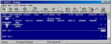
I am not sure if this is going to help you much, but here is a read of an analog genius block attached to a series 6 PLC (a bit old).

I will explain the 2 rungs shown.

Rung 1. This is a 'block move', this is the registers used for the 'data procesing request' DPREQ. We execute it this way to ensure that we are only reading the input values that we want to read, the registers in the block move are loaded with preset values to ensure that.

First we have the controlling logic to read the block, in this case we have used our 'POWERUP' bit, this bit is set after the first scan.
next we have a register address (starting address for the next seven registers) where the command block for the DPREQ is moved to.
The next seven registers (starting with the one containing the value 1833) are as follows:-

1. The bus controller address plus 1000
2. The command number, in our case 7 which means read analog status.
3. DPREQ status number - this is zeroed by the cpu, it is loaded by the bus controller at the end of the DPREQ.
4. This is the block I/O starting address (Input 385 in our case)
5. This is the register where you want the analogue data stored.
6. This is the length of the datagram being sent (if you are sending datagrams, which you won't be)
7. Not used.

Rung 2 is the data request rung, the value in hex will equal the value that is in the starting address of the registers used for the command block.

Well I am sure my explanation makes that as clear as MUD! That is obviously not one of my strong points, if you find it useful and you have any questions than ask away, perhaps Steve Bailey might be able to explain it a bit better

paul
analog.jpg
 
Last edited:
Thank you

Paul,

Thank you for the response. I'll be experimenting with those rungs shortly.

Regards,

Bruce
 
Older GE models like the Series Six handled analog signals differently than current models. In the Series 90, analog input signals show up as integers in %AIxxxx memory.

If you can give details of which hardware you're using, I can probably help. Do you need examples of how to use the values in ladder logic, how to scale the raw data to engineering units, or something else?
 
Analog inputs

Steve,

Thanks for the offer. Yes %AI are the register types. GE Fanuc 90-30 is the model. I'm writing a validation program. The only output is to a data panel. 16 4-20mA pressure transmitters are wired to a high density AI module. 48 discrete 24VDC inputs populate the rest of back plane. I'm OK with the Discrete IO. I've done enough of that. It's the Analog IO commands where I'm struggling.

For the first itteration I'm just planning to use a 4-20mA signal generator connected to a single AI (%AI0001) and have the data panel display the current value.

I had no problem embedding %R0001 to the display. but %AI0001 Remains Zero.

I'm going to attempt a rung of code with a data Move on the AI address out to a %M address and see if that creates a readable register for the data panel. This also should create a viewable register for the code to display.

Ultimately I will be doing complex math for signal conditioning and decision making (pass fail), but right now all I need is to get the first rung working.

Any suggestions or examples would be greatly appreciated.

Regards,

Bruce
 
%AI001 should display on the datapanel just as well as %R001. Have you verified that you are indeed seeing current flow at the input terminals and that you can see a value in %AI001 when monitoring the system using the programming software (LM90, VersaPro, or CME???).

Is your analog input module (IC693ALG223) configured properly, and did you store the configuration to the PLC? That module won't self-configure, and it defaults to only one active channel. With that particular module, you can also do scaling in the configuration file, so the data in the %AIxxx register is in engineering units rather than raw data value.
 
Analog inputs.

I have configured the module. I'm not sure whether the AI module requires 24VDC to be supplied. The signal generator is 24VDC battery operated, so I'm just applying it directly to the two input legs of the module for channel 1 (Screw 19 (-) and screw 3 (+) These appear to be Channel one.

I am able to verify signal generator operation via meter. I have not witnessed any register activity on AI0001 which is why I'm questioning it.

I have added a rung with AI yet. But that's my next trouble shooting step.

I will configure the module for engineering units per your suggestion.

Thanks
 
The module requires 24 VDC power connected between terminals 1 (+) and 19(Com). You can use the 24 VDC supply on the 90-30 power supply.

When you're connecting a self-powered transmitter, connect the + signal from the transmitter to terminal 3 for channel 1, the - signal to terminal 19.
 
Last edited:
Analog Input

My thanks to Steve and Paul and of course PLCS.net. I have begun my first tenitive steps with analog control. The issue appears to have been wiring and configuration. Specifically the module needed power and the configuration had to be switched from 4-20mA to 4-20mA+ :D
 
Analog Code Examples

Just in case anyone searching the archives needs this type of information. Attached is a ladder of GE fanuc 90-30 Analog input code. It converts 16 bit to 32 bit to avoid over flow errors. Then scales it to 3000 PSI, adds linear offset for calibration. Calculates 100 ms averages and deltas, and holds 5 second high and low deltas. Good Luck B.
 

Similar Topics

Hi All, I would like to ask you if possible to have some samples code for the realization of a software filter to be used in a PLC Micrologix...
Replies
2
Views
2,079
Help I have limited plc coding experience & need to input 0-10 volt dc analog into cscape to show results on meter screen. I have NO idea where to...
Replies
3
Views
2,769
I'm having trouble calming down 2 Tempo Sonics. I'm using Studio 5000 CompactLogix my Raw value is jumping around from 8575.0 to 8755.0 at a...
Replies
30
Views
1,136
I cannot add SLC500 analog input tag (I: 8.3) to EZSeries Touch Panel Editor (V 5.3). I used all the listed tag datatype but it all says "Invalid...
Replies
10
Views
257
Hi, I have questions. I have Analog Input that need to put into Ignition Designer. But I don't know how to put?
Replies
1
Views
119
Back
Top Bottom